 |
|||
|
|
|||
|
|
|||
| ||||||||||
|
|
 TM 10-3930-634-34
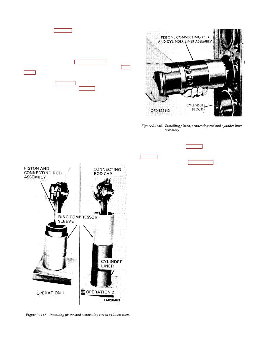
4. Hold the piston, rod, and liner in line with
the block bore (fig. 3-146) so the identification num-
ber on the rod is facing the engine serial number side.
Also, aline the matchmarks on the liner and block.
Slide the entire assembly into the block bore and seal
ring, being careful not to damage the seal ring.
5. Install the bearing shells and the connect-
ing rod caps as outlined in paragraph 3-35 f.
connecting rods (para 3-34 f).
3-39. Cylinder Block
a. General. The cylinder block is a one piece casting
which forms the main structural part of the engine.
Transverse webs provide rigidity and strength and in-
sure alinement of the block bores and bearings under
load. The block is bored to receive replaceable wet type
cylinder liners. A flat steel plate is bolted to the rear
end of the cylinder block to provide means of attaching
the flywheel housing, camshaft, and crankshaft cover.
b. Removal.
The cylinder block has drilled passages for carrying lu-
(1) Remove engine (para 2-5).
bricating oil to all moving parts, and fuel to the injec-
(2) Remove all subassemblies and components
tors.
c. Disassembly. Refer to figure 3-147 and disassem-
ble the cylinder block in numerical sequence as shown.
d. Cleaning.
(1) Remove all traces of gasket material from the
block. Use care to avoid damaging seal surface.
(2) Thoroughly clean cylinder and crankcase oil
passages using compressed air and brass wire probes.
Flush cylinder and crankcase water jacket thoroughly.
Clean block with live steam. Make sure oil galleries, air
box floor, and air box drain openings are thoroughly
cleaned. Jets machined in camshaft bushing bores per-
mit oil to be sprayed on cam followers; make sure they
are not plugged. A 0.020 inch wire may be used to
clean jets.
(3) Dry block with compressed air.
e. Testing.
(1) To perform the pressure test, it will be neces-
sary to make a steel plate of -inch stock to cover the
cylinder back of block. Plates will adequately seal top
surface of block when used with cylinder liner com-
pression gaskets and water hole cover plates and gas-
kets to seal water inlet openings in sides of block. One
cover plate must be drilled and tapped to provide a
connection for an air line so the water jacket can be
pressurized.
(2) Make sure the seal ring grooves in cylinder
liner bore of block are clean. Install seal rings in the
grooves.
(3) Apply a light coating of vegetable type short-
ening or permanent type antifreeze solution to the in-
|
|
Privacy Statement - Press Release - Copyright Information. - Contact Us |
