 |
|||
|
|
|||
|
Page Title:
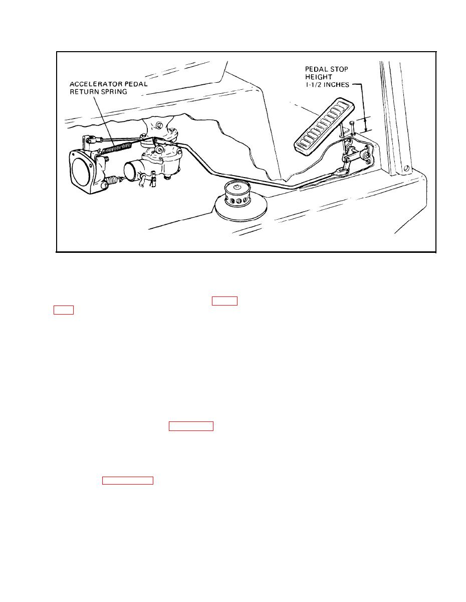
Figure 4-56. Pedal and Linkage Adjustment |
|
||
| ||||||||||
|
|
 Figure 4-56. Pedal and Linkage Adjustment
h. Check the engine idle (hot engine) speed and
finger at (2) until breakover arm (3) contacts
adjust it to specifications, if necessary. See figure
governor arm (4).
e . Adjust clevis (5) to obtain 1:32 of an inch
j. Place the transmission selector lever in neutral.
clearance at (6).
Shut off the engine and switch off the headlamp.
Remove the tachometer.
f. Then, adjust the accelerator pedal clevis (7) to
obtain l/32 of an inch clearance at the carburetor
4-56. GOVERNOR
throttle shaft breakover arm (8).
AND
LINKAGE
ADJUSTMENTS. The governor of this engine is
external and is a flyweight type driven off the idler
g. Start the engine and check no-load maximum
p u m p drive gear. It is extremely accurate when
governed speed, which should be 2350 RPM. If this
properly set, and is adjusted as follows:
s p e e d is low, adjust governor spring tension at
point (1) by loosening locknut on adjusting rod,
a. With engine shut down, remove the accelerator
and tightening adjusting nut until proper engine
pedal return spring, as shown in figure 4-56.
speed is obtained.
b . Then
check
and,
if necessary,
adjust
h . Tighten locknut at point (1) securely after
accelerator pedal stop height which must be l-1/2
adjusting spring tension.
inches.
4-57. STEERING SYSTEM MAINTENANCE.
c. Refer to figure 4-57 and adjust governor
linkage as follows;
4.58. ADJUSTMENT CHECK. The following
check may be made to determine if steering system
d. With governor spring (1) connected, push with
is operating within original design limits.
4-41
|
|
Privacy Statement - Press Release - Copyright Information. - Contact Us |