 |
|||
|
|
|||
|
Page Title:
Section III. TRANSMISSION AND TORQUE CONVERTER |
|
||
| ||||||||||
|
|
 TM 10-3930-630-34
NOTE
12-7.
Transmission Control Valve, Cleaning,
Check all plungers and spools to be
Inspection and Repair
a. Wash all metal parts in cleaning solvent, (Fed.
certain they operate freely.
Be
Spec. P-D-680) and dry with compressed air.
certain the inching control plunger
b. Blow out all passages in the valve body with
stop is installed with the angled
compressed air.
edges facing toward the rear of the
c. Check plungers and spools for scratches or
valve body.
scoring, clean with crocus cloth. If severely damaged,
b. Installation.
replace.
(1) Remove covering from transmission and
d. Check springs for cracks, breaks or other
install a new gasket.
damage. Replace if necessary.
(2) Refer to figure 12-4 and position control
e. Replace all gaskets, seal rings, and oil seals at
valve on transmission and secure with mounting screws.
reassembly.
Torque screws to 5 to 10 foot-pounds (6.7 to 13.5 N-m).
(3) Remove cap from tube assembly and
12-8.
Transmission Control Valve, Reas-
connect assembly to the control valve.
sembly and Installation
(4) Reconnect control linkage to control valve.
(5) Refer to paragraph 12-12b for test and
a. Reassembly. Reassemble transmission control
adjustments, if necessary.
valve in reverse numerical sequence as illustrated in
(6) Refer to TM 10-3930-630-12 and install
floor and toe plates.
Section III.
TRANSMISSION AND TORQUE CONVERTER
12-9.
General
(4) Remove tube assembly (1, fig. 12-7) and
elbow (2). Remove oil level gage (68) and plugs (64,
65, 66 and 67). Remove pipe plug (61) and remove
converter which, in turn, drives a pump and clutch pack.
spring (62) and screen (63). Remove seat (16), washer
Housed in the clutch drum are two double faced clutch
(17), spring (18), and ball (19) from converter housing.
plates which, when activated, move the truck forward or
in reverse through splined hubs transmitting power to
the gear train.
b. If the reverse clutch is activated, power is
delivered to the transmission through a hollow shaft
which connects the reverse gear and reverse clutch. If
the forward clutch is actuated, power is delivered to the
transmission through a solid shaft, which rotates inside
the hollow reverse shaft connecting the forward gear
and forward clutch.
12-10. Transmission and Torque Converter,
Removal and Disassembly
the transmission.
b. Disassembly.
(1) Clean the exterior of transmission with
cleaning solvent, (Fed. Spec. P-D-680) to prevent
system contamination.
(2) Refer to paragraph 12-6 and remove the
transmission control valve.
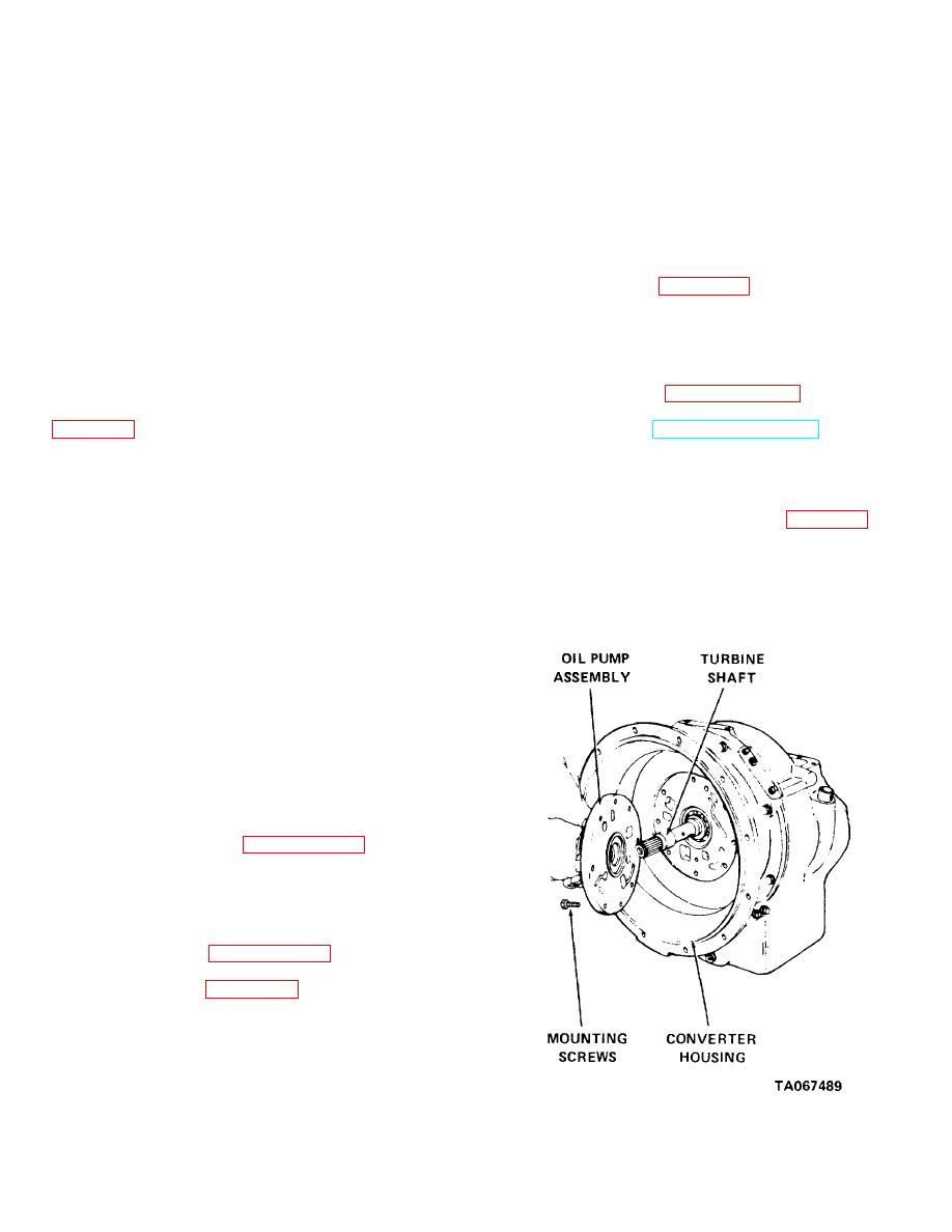
(3) Refer to figure 12-6 and mark oil pump
assembly and housing to insure proper reassembly.
Remove mounting screws holding oil pump assembly to
converter housing. If necessary, tap pump assembly
with a rawhide hammer to free it from the gasket.
Figure 12-6. Transmission oil pump, removal and installation.
12-6
|
|
Privacy Statement - Press Release - Copyright Information. - Contact Us |