 |
|||
|
|
|||
|
Page Title:
Transmission and Torque Converter, Cleaning, Inspection and Repair |
|
||
| ||||||||||
|
|
 TM 10-3930-630-34
(e) Turn drum over and remove screws
(13), lock plates (14), retaining ring (15), rear cylinder
(16), piston (19), and reverse disc (20). Remove
packings (17 and 18). Remove pins (21) from pressure
plate (22). Remove roller bearing (23) from rear
cylinder.
12-11. Transmission
and
Converter,
Cleaning, Inspection and Repair
a. Wash all metal parts with cleaning solvent,
(Fed. Spec. P-D-680) and dry thoroughly.
b. Blow out passages with compressed air.
gears for wear or damage and replace if damage is
severe.
d. Inspect sump screen for clogged or damaged
screen and replace if necessary.
TA067494
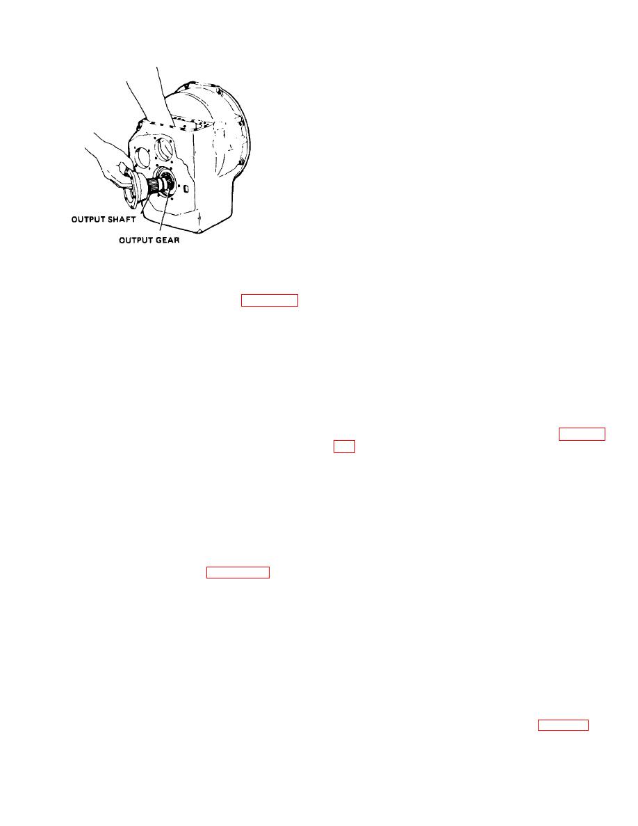
Figure 12-11. Removing output shaft and gear.
excessive wear or score marks. Replace if necessary.
f. Check piston rings making certain they are free
in piston grooves.
holding output shaft retainer (53) to housing.
g. Replace all seals and packings.
(b) Remove output shaft (57) and
retainer (53), while holding output gear (60) inside gear
12-12. Transmission
and
Converter,
box. It may be necessary to tap the output shaft from
inside the clutch housing to facilitate removal.
Reassembly and Installation
(c) Remove output gear (60).
a. Reassembly.
(11) Drum assembly which was removed in (6)
(1) Assemble the drum assembly:
above can now be disassembled.
(a) Check etched or scribed marks on
CAUTION
pistons and cylinders. Align marks before assembling
The front and rear clutch assemblies
are balanced. Two lines are etched
on rear clutch cylinder to indicate
roller bearing (23) and rear cylinder (16). Make certain
correct align-ment of the cylinder
the rear cylinder and the piston do not bind in the drum
with the piston. One etched line is
or on the dowel pins. Install large retaining ring (15)
used to indicate correct alignment
holding cylinder and assembled parts in place.
for forward clutch cylinder with the
(c) Turn the drum assembly over and
piston. If etched marks cannot be
install the springs (12), forward disc (11), piston (10),
located, punch or scribe marks on
new packings (7 and 8) and the front cylinder (5).
the cylinders and piston to insure
(d) Install bearing (9) in turbine shaft (6).
proper alignment during reassembly.
Place the entire assembly in an arbor press. Apply
(a) Place the drum assembly in an arbor
pressure on the turbine shaft, making certain the
press. Remove seven screws (4, fig. 12-12), apply
cylinder does not bind in the drum or on the dowel pins
pressure on the turbine shaft (6) until the cylinder is
(21). Install retaining ring (1), lock plates (3) and screws
depressed enough to remove the large retaining ring (1)
(2). Install screws (4) to secure turbine shaft.
from the drum. Remove turbine shaft (6). Remove
(e) Check to be certain the front cylinder
roller bearing (9).
is properly seated and release arbor press pressure.
(b) Remove screws (2) and lock plates
(3) from cylinder.
(2)
Assemble the output gear and shaft:
(c) Slowly release the arbor press
NOTE
pressure and remove front cylinder (5) making sure it is
Apply a coat of lubricant (OE/HDO) to
kept in alignment to prevent binding in the drum. If
binding occurs, tap cylinder lightly with a rawhide
installation.
hammer until it is released. Remove packings (7 and
8).
(d) Remove piston (10), forward disc (11)
transmission case and install output gear shaft
and springs (12). Take care that piston ring is not
damaged or binding during removal.
12-9
|
|
Privacy Statement - Press Release - Copyright Information. - Contact Us |