 |
|||
|
|
|||
|
|
|||
| ||||||||||
|
|
 TM 10-3930-630-12
speed of the truck engine. Depressing the pedal
(3) Remove hose (3) and elbow (4) from
increases the speed. A cable connects the pedal to the
manifold.
c. Installation.
carburetor. The cable is in turn connected to a return
spring and bracket.
(1) Install elbow (4, fig. 449) in tapped hole in
manifold (11)
the accelerator cable.
(2) Connect hose (3) to elbow and install valve
c. Removal
(2) in hose.
(3) Connect valve to valve chamber cover
(1) Remove floor and toe plates.
with hose (1). (4) Close side panel.
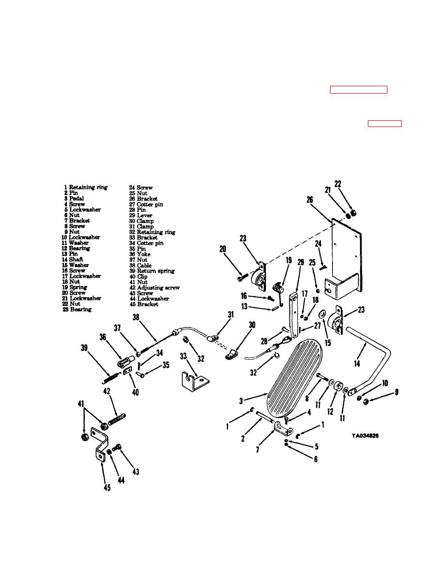
(2) Remove retaining rings (1, fig. 4-50) and
pin (2). Remove pedal (3) from toe plate.
4-63.
Accelerator Pedal and linkage
a. General The accelerator pedal controls the
.
Figure 4-50. Accelerator linkage, exploded view.
4-59
|
|
Privacy Statement - Press Release - Copyright Information. - Contact Us |
