 |
|||
|
|
|||
|
|
|||
| ||||||||||
|
|
 (2) Remove the cylinder head from the engine
b. Cleaning and Inspection.
block, (TM 10-3930-627-12).
(1) Clean oil pump parts and screen with solvent
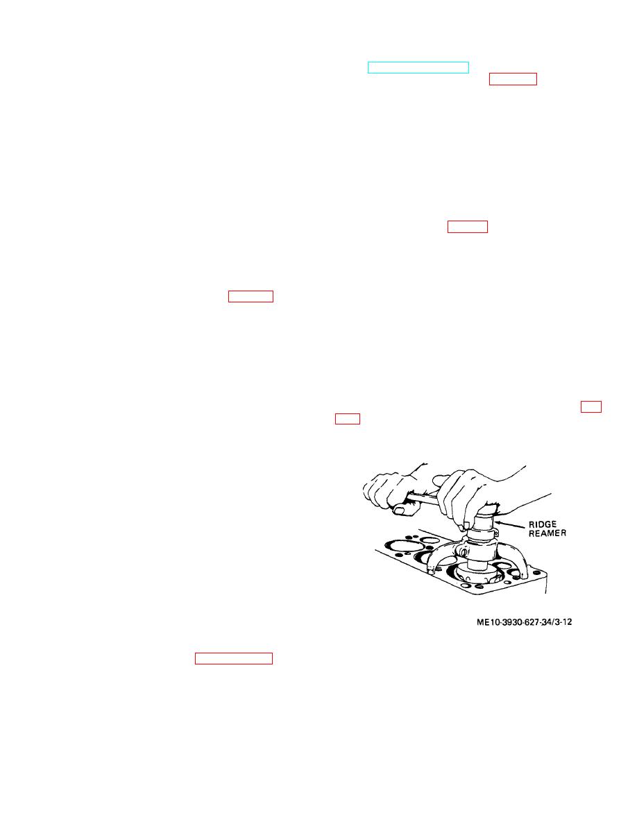
(3) Using a ridge reamer (fig. 3-12), remove the
and brush.
ridge from inside the top of the cylinder bore.
(2) Inspect pump gears and drive shaft. If pump
is defective, install a new pump.
(3) Inspect screen for holes and clean mesh. If
Note.
the mesh is defective, replace the screen with a
Ridge must be completely removed
serviceable one.
before trying to remove pistons to
(4) Thoroughly wet all parts of the pump with
avoid breaking rings and the piston
clean engine oil prior to installation to ensure that pump
lands
between
ring
grooves;
will operate immediately when starting engine.
however, do not cut deeper than
c. Installation. Reverse step a. above. If pump drive
worn part of cylinder wall.
slot does not engage distributor without turning rotor,
reengage gear teeth in different positions until oil pump
(4) Turn crankshaft throws to lowest points, and
is installed without changing ignition timing.
remove cotter pins (28, fig. 3-4) and nuts (27) from the
connecting rod bolts (26) and remove the lower bearing
3-11. Oil Pressure Relief Valve
caps and bearing halves (24) from the connecting rods
a. Removal.
(23).
(5) Push the connecting rods and pistons out of
carburetor.
the top of the cylinder bore.
(2) Remove relief valve plug (34, fig. 3-11), with
(6) Temporarily install the connecting rod bearing
gasket (33), from engine block (5). Remove gasket
caps on the connecting rods from which they were
from plug.
removed.
(3) Remove the adjusting washer (31) (if there is
(7) Using a ring spreader, remove the piston rings
one) from the plug.
(32) from the pistons (29), or simply break rings off, if
(4) Remove the spring (32) and valve (30) from
they will not be reused.
the port in the engine block. Remove washer from
(8) Remove the piston pin retaining rings (31) and
valve (if there is one).
remove the pins from the pistons, separating the
b. Cleaning. Clean all metal parts in solvent and dry
connecting rods from the pistons. Press the bushings
with compressed air or clean lint-free cloth.
(25) from the connecting rods, using new bushings (fig.
c. Inspection. Inspect the valve for scoring or pitting.
Inspect the spring for distortion.
operation.
d. Installation. Reverse step a. above, adding or
removing washers or installing new spring to obtain
desired pressure setting. Up to four washers are
permitted. The oil pressure relief valve setting is 25 to
35 psi with the engine oil at normal operation
temperature at governed speed.
3-12. Pistons, Connecting Rods and Rod Bearings
a. Description. Each piston has two compression
rings and two oil rings. The full floating piston pins are
held in place by retaining rings. The connecting rods
use babbitt lined sleeve bearing pairs. The connecting
rods and the connecting rod bearing caps are matched
and numbered.
Numbered sides must face the
camshaft when reinstalled. Never reverse or exchange
bearing caps.
b. Removal. To service pistons, rod and cylinders,
the engine need not be removed from the truck.
Figure 3-12. Reaming ridge from cylinder.
(1) Remove the oil pan. Paragraph 3-9 a. as
applicable.
3-10
|
|
Privacy Statement - Press Release - Copyright Information. - Contact Us |