 |
|||
|
|
|||
|
Page Title:
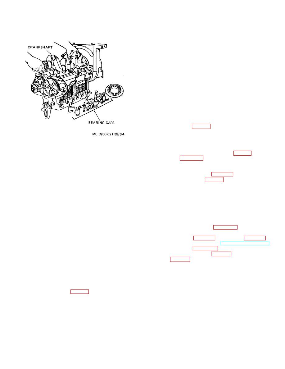
Figure 3-4. Crankshaft removal. |
|
||
| ||||||||||
|
|
 TM 10-3930-621-34
c. Take a dial indicator reading at center main bearing
journal. Maximum taper or out-of-round allowable during
one revolution is 0.002 of an inch.
d. Check remaining connecting rod and main bearing
journals for out-of-round and tapered condition.
Maximum variation allowable from center main bearing
journal reading is 0.0005 of an inch.
e. The crankshaft shall be examined for alignment,
cracks, and breaks. If none of the above damages are
found, the crankshaft may be rehabilitated.
The
crankshaft may be rebuilt to standard size by Hard
Chrome Plating or sub-merged arc welding, or the
crankshaft may be ground to undersize 0.010 or 0.020 of
an inch. The method of repair used shall be by the
availability of facilities, and the cost factor.
f. Replace parts as authorized.
3-11. Installation
a. Insert key (1., fig. 3-3) in crankshaft (7) and tap
gear (11) in place with rubber mallet.
b. Slowly lower crankshaft on bearing seats, avoiding
any bumping of bearing or journal surfaces.
Figure 3-4. Crankshaft removal.
c. Install bearings (8, 9 and 10).
d. Install main bearings (11, 24, 30, fig. 3-2)and rod
3-9. Cleaning
bearing caps (para 3-30). Torque main bearings 88 to
a. Clean all parts with a cleaning compound, solvent
92 and rod bearings 44 to 46 foot-pounds.
(Spec. P-S-661). Dry thoroughly with compressed air.
e. Initial main bearing lock plates (29).
b. Remove all dirt and foreign matter from inside
f. Install timing gear cover (para 3-39).
hearing caps.
g. Insert gear key (17, fig. 3-3) into crankshaft and
c. Using a soft wire probe, clean all passages.
press on drive gear (11). Aline "C" marks on crankshaft
3-10. Inspection and Repair
and camshaft gears and mesh gears.
a.
Inspect crankshaft journals and bearings for
h. Insert pulley key and press on pulley-deflector
excessive wear, scoring, taper, out-of-round, and other
assembly (12, 14).
possible damage.
i. Secure gear and pulley with nut (16) and washer
b. Mount the crankshaft in "V" blocks at the front and
(15).
rear main bearing journals. To avoid marring shaft,
j. Install deflector (6), oil seal (5), gasket (4).and
insert paper strips soaked in lubricating oil in "V" blocks.
closure plate (3) on other end of crankshaft.
k. Secure oil pan in plate (para 3-40) and fill with
specified oil.
l. Install flywheel (para 3-15) and governor(para 4-19).
m. Install engine accessories (TM 10-3930-621-12)
and hydraulic pump (para 10-42).
n. Install engine assembly (para 2-5) and transmission
assembly (para 2-6) in truck.
Section IV. FLYWHEEL ASSEMBLY AND HOUSING
rear end of the crankshaft. A timing strip is secured to
3-12. Description
the flywheel for more accurate engine timing.
a.
Flywheel Assembly.
The flywheel assembly
b.
Flywheel Housing.
The flywheel housing is
consists of a flywheel (1, fig. 3-5) and a ring gear (2),
attached to a machined surface on the rear of the engine
which is shrunk fit to the flywheel.
The flvwheel
block. An opening, with access cover, is
assembly is secured to a flange on the
3-6
|
|
Privacy Statement - Press Release - Copyright Information. - Contact Us |