 |
|||
|
|
|||
|
|
|||
| ||||||||||
|
|
 TM 10-3930-621-34
provided through which the timing marks on the
3-13. Removal
timing strip may be seen. Two engine mounting
a. Remove engine assembly from truck (para 2-5).
b. Remove transmission from engine (para 2-6).
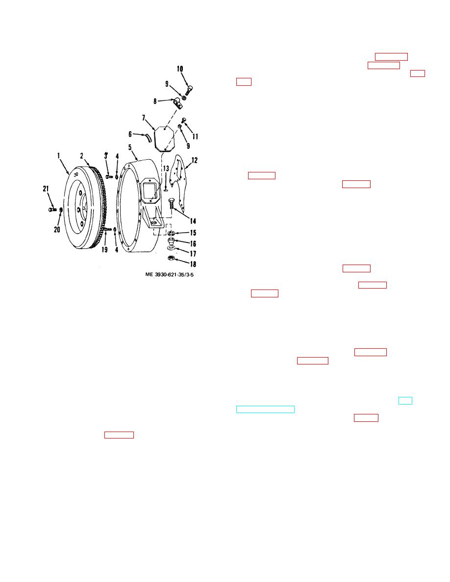
c. Remove the lockwires from the four bolts (21, fig.
flywheel to flange.
Caution: Do not mix special fly wheel
retaining bolts (21) with others. Do not use ordinary
bolts, since flywheel bolts are under great stress in
normal use.
d. Remove flywheel (1).
e. If necessary to remove starter ring gear (2), heat
gear and cut out with chisel.
f. Remove the three bolts (9O) and lock washers
(4) holding the main bearing assembly closure plate
(3, fig. 3-3) and remove plate.
g. Remove the five screws (3, fig. 3-5) and lock
washers (4) holding the flywheel housing t5) to the
cylinder block and remove housing.
3-14. Cleaning and Inspection
a. Clean all parts with a cleaning compound, solvent
(Spec. P-S-661). Dry thoroughly using compressed air.
b. Check ring gear for cracks, chipped teeth, and
other damage or wear.
c. Replace damaged parts as authorized.
3-15. Installation
a. Install flywheel housing (5, fig. 3-5) on engine block
with screws (3) and lock washers (4).
b. Install bearing closure plate (3, fig. 3-3) with bolts
3. Screw
14.
Mounting cap screw
(19, fig. 3-5) and lock washers (4).
4 Lock washer
15.
Alining washer
c. Heat starter ring gear (2) and press gear on
5. Flywheel housing
16.
Mount
flywheel.
6. Timing strip
17.
Flat washer
d. Install flywheel (1 ) and secure with bolts (21 )and
7. Access cover
18.
Self-locking nut
lock washers (20). Be sure to use special flywheel
8. Loop clamp
19.
Closure machine bolt
9. Lock washer
20.
Flywheel lock washer
bolts.-
10. Machine bolt
21.
Flywheel bolt
e. Install lockwires on bolts (21).
11. Machine bolt
f. Install transmission on engine para 2-6)and engine
assembly in truck (para 2-5).
Figure 3-5. Flywheel assembly, exploded view.
Section V. VALVES, SPRINGS, GUIDE, SEATS AND TARPET ASSEMBLIES
(2) Remove valve covers on side of engine block (TM
3-16. Description
10-3930-621-12).
(3) Raise spring retainer (5, fig 3-6) until the two
The valve tappets and valves are of the mushroom type.
wedge shaped lock, (6, drop out from between the cap
Valve springs are held to the valve stem by a pair of
(7) and retainer.
wedge shaped locks (6, fig. 3-6) between the stem and
(4) Lift valves (1), retainer caps (7) , retainers
spring retainer (5). The valves operate in replaceable
(5), and springs (4) out of engine.
guides (2) and (3) and seats.
(5) Place valves in numbered holes., in a board
3-17. Valves and Springs
to make sure of reinstallation in their original positions.
a. Removal.
(1) Remove cylinder head (TM 10-3930-621-
12).
3-7
|
|
Privacy Statement - Press Release - Copyright Information. - Contact Us |