 |
|||
|
|
|||
|
Page Title:
Section III. CRANKSHAFT, BEARING, AND TIMING GEAR |
|
||
| ||||||||||
|
|
 TM 10-3930-621-34
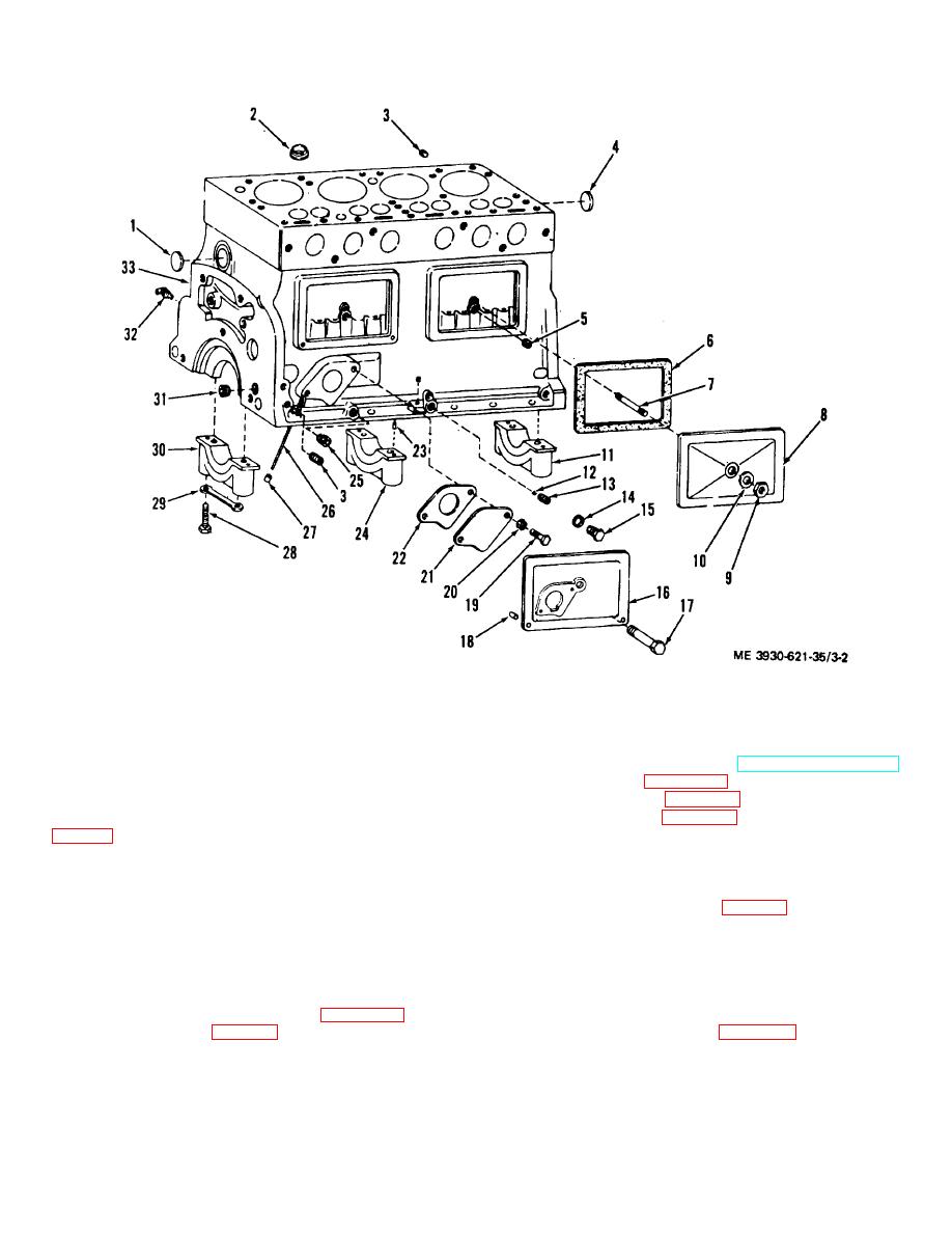
Figure 3-2. Engine block and associated parts, exploded view.
Section III. CRANKSHAFT, BEARING, AND TIMING GEAR
b. Remove engine accessories (TM 10-3930-621-12)
3-7. Description
and hydraulic pump (para 10-38).
The crankshaft is a heat treated steel forging, drilled for
c. Remove governor (para 4-15).
rod and bearing pressure lubrication. End thrust is
d. Remove flywheel (para 3-13).
controlled by the flanges of the center main bearing 19,
e. Drain oil remove oil pan. Turn engine upside down
only if more convenient.
place. The crankshaft pulley(14) is keyed, supports a
Caution: Protect machined surfaces, moving parts,
deflector (12), and is pressed on the portion of the
crankshaft protruding through the timing gear. Another
and openings from dirt and damage.
deflector (6) is pressed into place on the flywheel end of
f. Remove bearing plate (3, fig. 3-3), gasket(4), oil
the crankshaft. The precision type main bearings (8, 9,
seal (5), and deflector (6).
and 10) consist of thin wall bearing shells held in place
g. Remove crankshaft pulley (14) with attached
by precision machined bearings seats and caps.
deflector (12) by removing nut (16) and washer(15) and
using a suitable gear puller to remove the pulley.
h. Remove drive gear (11) and key (17) using suitable
3-8. Removal
gear puller.
a.
Remove engine assembly (para 2-5) and
i. Remove timing gear cover (para 3-37).
transmission assembly (para 2-6), from truck.
3-4
|
|
Privacy Statement - Press Release - Copyright Information. - Contact Us |