 |
|||
|
|
|||
|
Page Title:
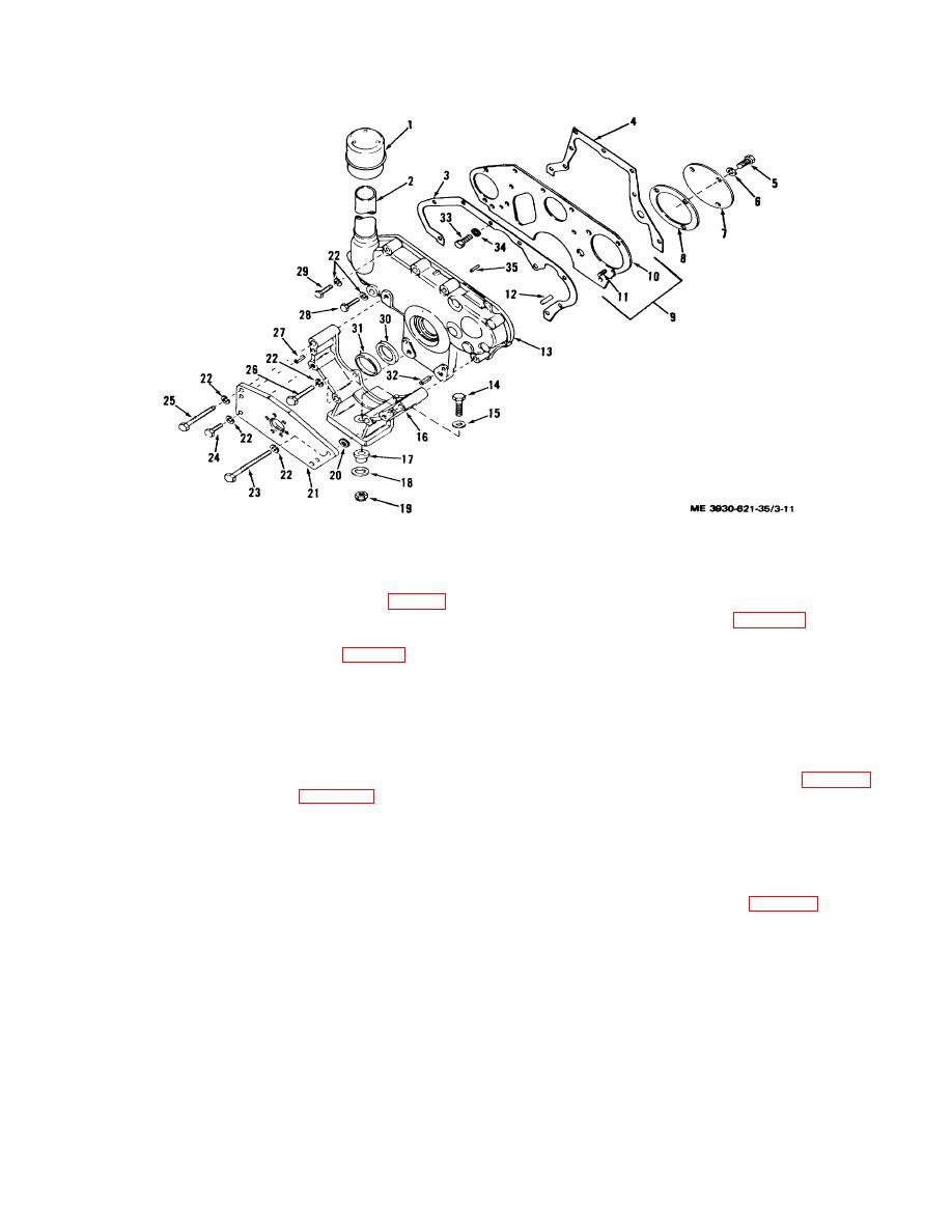
Figure 3-11. Timing gear cover, exploded view. |
|
||
| ||||||||||
|
|
 TM 10-3930-621-34
Figure 3-11. Timing gear cover, exploded view.
b. Crankshaft, Camshaft and Governor Gears.
3-39. Installation
(1) Remove camshaft retaining ring (17, fig. 3-6)
a. Crankshaft, Camshaft and Governor Gears.
and, using a suitable gear puller, remove camshaft gear
(1) Install governor gear (para 4-19).
(16).
(2) Heat carp and crankshaft gears to
(2) Remove front deflector (1;, fig. 3-3) with
approximately 4500 F. in an oil bath. Use a driving
attaching drive screws (13).
sleeve to tap gear snuggly in place. Hard driving is not
(3) Using a suitable gear puller remove
normally necessary and indicates the gear is too cold or
crankshaft gear (11).
cocked on shaft. Aline "C" marks on gears and mesh
Note. If suitable gear puller is not available, gear
gears for proper timing.
may be removed by drilling at the keyway and splitting
(3) Install deflector (12,fig.3-3) on crankshaft
the gear. Drill directly above key to avoid damage to
and secure with screws (13).
shaft.
(4) Secure camshaft gear (16, fig. 3-6) to
(4) Remove governor gear (para 4-15).
camshaft with retaining ring (17).
3-38. Cleaning and Inspection
(5) Check gears for backlash of 0.002 to 0.004
a. Clean all parts with cleaning compound, solvent
inch. Looser fits are tolerable provided looseness is not
(Spec. P-S-661). Dry thoroughly with compressed air.
so excessive as to cause chatter. A slightly loose fit is
b. Inspect gears for cracks, chips or other signs of
preferable over a tight fit.
excessive wear and damage.
b. Timing Gear Cover.
c. Inspect cover for cracks, dents, breaks and other
(1) Insert spring pin (32, fig. 3-11) and cover
damage.
(13) and install cover and gasket (3) on front plate (10)
d. Replace defective parts as authorized.
and secure with screws (28 and 29) and lock washers
(22).
(2) Install oil breather cap (1), oil seal (30), and
oil seal retainer (31) on timing gear cover.
3-16
|
|
Privacy Statement - Press Release - Copyright Information. - Contact Us |
