 |
|||
|
|
|||
|
|
|||
| ||||||||||
|
|
 TM 10-3930-621-34
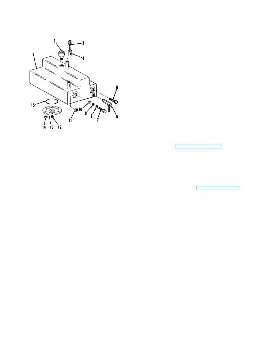
10-36. Installation
a. Refer to figure 10-10 and install as follows:
b. Using care not to damage tubing, lift reservoir (1)
into position at bottom of truck and secure it with long
screws (6), short screws (7), lock washers (9), flat
washers (8), bushings (10), and nuts (11). Use long
screws (6) on frame crossmember side of reservoir.
Note. Mounting clips are on lower portion of tank on
crossmember side.
c. Secure drain cover (13) and new packing (15) to
bottom of reservoir (1) and install drain plug (12) in
cover.
d. Secure elbow (5) in coupling at side of reservoir
and attach power steering hydraulic line to elbow.
e. Check that reservoir is securely mounted and
then lower truck to floor.
f. Connect suction and return hydraulic lines to
connections at top of reservoir (1).
Note. Suction line is the larger of the two lines and
fits the bent tubing on the crossmember end of the
ME 3930-621-35/10-10
reservoir.
g. Install breather (2) and screen (4) in reservoir.
1.
Reservoir
9.
Lock washer
h. Refer to TM 10-3930-621-12 and fill reservoir
2.
Breather
10.
Bushing
with specified hydraulic oil.
3.
Gage
11.
Nut
Caution: NEVER USE BRAKE FLUID. When
4.
Screen
12.
Plug
filling tank, make sure containers and surrounding
5.
Elbow
13.
Cover
parts are clean, to prevent oil contamination. Any
6.
Screw, long
14.
Nut
hydraulic oil used must contain a rust preventative
7.
Screw, short
15.
Packing
and an oxidation inhibitor. The oil should not foam.
8.
Flat washer
i. Install gage (3) in tank.
j. Install floor plates (TM 10-3930-621-12).
Figure 10-10. Hydraulic reservoir, exploded view.
Section VIII. HYDRAULIC PUMP
power steering gear when the steering gear is operated.
10-37. Description
If pressure above 2000 psi develops when control levers
The hydraulic pump is a gear type unit, driven directly
are operated, it is by-passed at the control valve.
through a coupling from the engine crankshaft.
Reservoir oil is drawn through a suction port and directed
10-38. Removal
by a spool to the power steering port at a maximum
a. Refer to figure 10-11 and remove as follows:
pressure of 1200 to 1300 psi with engine speed at 1400
b. Remove radiator grille guard (TM 10-3930621-
rpm. When a specified flow is reached, the relief valve
12).
spring in the control valve compresses, allowing the
c. Disconnect hydraulic lines to power steering
spool to reposition and direct flow to the control valve
gear, control valve, and suction ports (TM 103930-621-
port. A check valve on the power steering port of the
12).
pump maintains a steady 1000 to 1300 psi to the
10-20
|
|
Privacy Statement - Press Release - Copyright Information. - Contact Us |
