 |
|||
|
|
|||
|
Page Title:
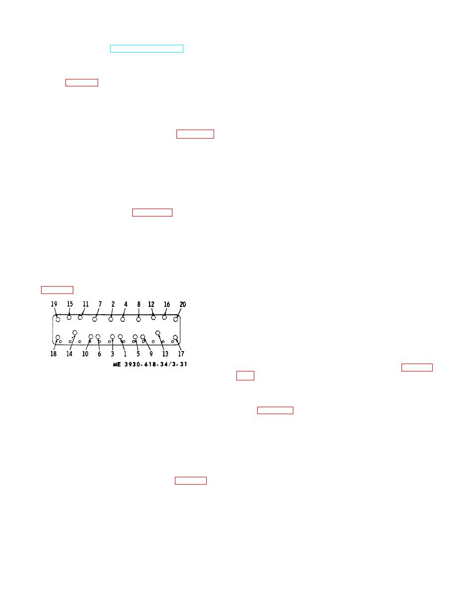
Figure 3-31. Sequence for cylinder head Capscrew tightening. |
|
||
| ||||||||||
|
|
 (e) Remove spark plug cables.
3. Retighten capscrews in numerical
(f) Remove radiator connections to
sequence to full recommended torque.
4. Run
engine
until
coolant
engine and transmission (TM 10-3930-618-20).
temperature reaches minimum of 160F, (approx. 1
(g) Disconnect rocker arm oil feed line
from head and move out of way.
hour), then retorque capscrews to the full recommended
(h) Remove cylinder head capscrews
torque in the specified numerical sequence.
(11 and 16, fig. 3-30), nuts (5) and washers (6, 10, and
(g) Reset the valve tappet clearance.
17). Lift cylinder head assembly (19) from block with a
b. Cylinder Block and Cylinder Sleeves.
sling. Discard fire rings (23) and head gasket (24).
(1) Description. The cylinder block is a one-
(4) Inspection of cylinder head.
piece iron casting. Integral transverse members provide
(a) Clean cylinder head, removing all
rigidity and strength, assuring accurate alignment of
carbon deposits, and inspect for wear or other damage.
crankshaft bearings and cylinder sleeves. Block is bored
(b) Before removing valves (para 3-23)
to receive removable cylinder sleeves which are
check them for seating.
completely surrounded by full-length water jackets for
(c) Replace defective parts.
maximum cooling.
The main oil gallery extends
NOTE
lengthwise through the cylinder block, below and parallel
If cylinder head is to be replaced,
to the camshaft. Oil passages direct oil from main oil
parts from the defective head must
gallery to main bearings. A horizontal oil passage leads
to the outside of the cylinder block and is connected by
be thoroughly inspected before
tubing to lubricate rocker arm assembly. The removable
installing them in a new head. For
cylinder sleeves are made of alloy cast iron. Two
inspection procedures for valves and
silicone rubber packing rings, fitted into grooves in lower
rocker arm assembly (para 3-23) and
bore of cylinder block, prevent water leakage into
for spark plugs, see TM 10-3930-618-
crankcase. Sleeve is seated at top by a flange which fits
20.
into a machined recess in block. Cylinder head gasket
(5) Installation of cylinder head.
and fire rings are compressed between this flange and
(a) Thoroughly clean the top deck of the
cylinder head, holding sleeve in place.
cylinder block and the underside of the cylinder head.
(2) Removal of cylinder sleeve.
(b) Do not use any sealer or gasket
NOTE
dope on any part of the cylinder head gasket assembly.
When removing sleeves and pistons.
(c) Install guide studs in holes (19 and
do not interchange parts.
If any
20. fig. 3-31).
sleeves are to be reused, they should
be reinstalled in the same sleeve bore
from which the)y were removed.
Pistons must be reinstalled in the
same sleeves from which they were
removed.
If engine has already been removed from truck,
disregard (a) below.
(a) Remove engine from truck (para 2-
Figure 3-31. Sequence for cylinder head Capscrew
(b) Remove cylinder head assembly
tightening.
(para a above).
(c) Remove pistons and connecting
(d) Position the head gasket on the
rods (para 3-22).
cylinder block guide studs. Position the fire rings inside
(d) Rotate crankshaft to gain access for
the cylinder bores of the gasket and be sure no
installation of cylinder sleeve puller.
overlapping of the fire rings by the gasket occurs.
(3) Cylinder sleeve tool. Install puller tool to
(e) Carefully install the head, being sure
remove cylinder sleeve from top of cylinder block.
not to displace the positioned fire rings. Head is to be
NOTE
located by the guide studs. Install capscrews in all
If sleeve puller is not available, sleeves
locations except those occupied by guide studs.
may be loosened by placing end of
(f) Torque the capscrews to a final
hardwood block against bottom of sleeve
torque of 110 ft-lbs. in the following manner (fig. 3-31).
and striking block sharply with a
1. Tighten capscrews in numerical
hammer. Be careful not to hit cylinder
sequence to 1/2, final torque. Remove guide studs and
block.
install lifting studs when reaching these locations.
(4)
Cleaning and inspection of cylinder
2. Tighten capscrews in numerical
sleeves.
sequence to full recommended torque.
3-37
|
|
Privacy Statement - Press Release - Copyright Information. - Contact Us |
