 |
|||
|
|
|||
|
Page Title:
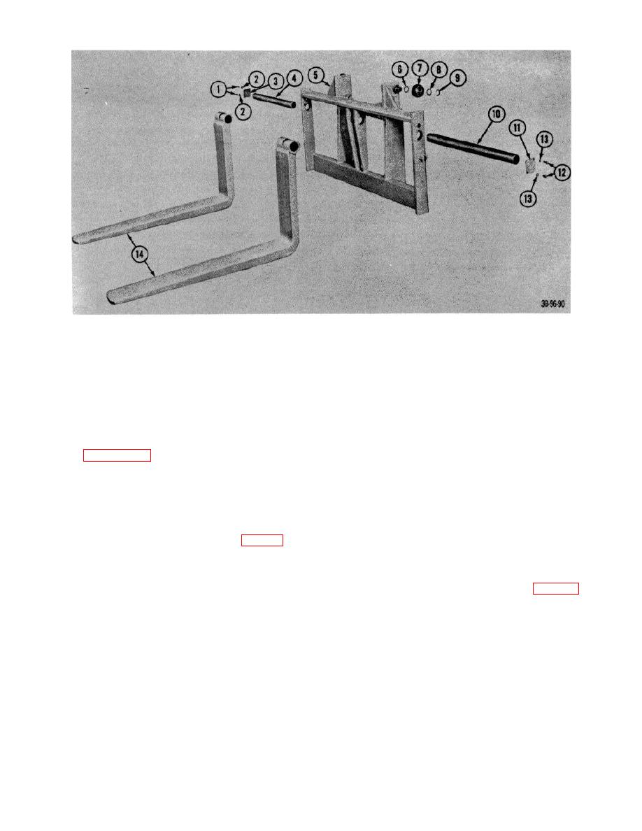
Figure 102. Fork carriage, exploded view |
|
||
| ||||||||||
|
|
 1
Capscrews
8
Shim
2
Lockwasher
9
Ring, retaining
8
Plate, keeper
10
Pin, load fork
4
Pin, load fork
11
Plate, keeper
5
Frame, carriage
12
Capscrews
6
Shim
13
Lockwasher
7
Roller, load
14
Forks, load
Figure 102. Fork carriage, exploded view
(7) Turn screws though center of carriage,
69. Crank Assembly and Lead Screws
either to right or to the left, until nuts
Refer to figures 102 and 103 and remove crank
(2 and 9) can be removed from
assembly and lead screws as follows:
screws.
a.
Removal.
(8) Remove screws from carriage. Drive
bushings (4 and 7) from carriage.
(1) Remove load fork (TM 10-3930-222-
20).
b. Installation Reverse procedures in a above.
(2) Turn crank handle until left-hand and
right-hand nuts (2 and 9, fig. 103) are
70. Cable Chain
positioned about three inches from
left and right edge of carriage.
a.
Removal.
(3) Remove spring pin (5) from collar (6)
that connects the lead screws (3 and
(1) Unscrew stop nuts (2, fig. 104) that
8).
secure chains (1) to lift carriage.
(4) Remove spring pin (11) that connects
(2) Unscrew stop nuts that secure chains
handle to screw (8) and remove
to hoist cylinder and remove washers
handle.
(5) and chains from hoist cylinder
(5) Hammer on crank end of screw (8)
brackets.
with proper tool to remove bushing (1)
(3) Remove cotter pin from straight pin
from opposite end of carriage.
(3) and remove in from anchor (4).
(6) Hammer on other end of screw (3)
(4) Remove chain from anchor.
with proper tool to remove bushing
(5) Remove chain from roller s on mat.
(10) from opposite end of carriage.
AGO 7010A
123
|
|
Privacy Statement - Press Release - Copyright Information. - Contact Us |