 |
|||
|
|
|||
|
Page Title:
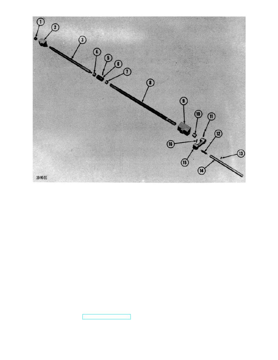
Figure 103. Crank assembly and lead screws, exploded view. |
|
||
| ||||||||||
|
|
 1
Bushing
9
Nut, left-hand lead screw
2
Nut, right-hand led screw
10
Bushing
3
Screw, lead, right-hand fork adjusting 11
Pin, spring
4
Bushing
12
Spring
5
Pin, spring
13
Capscrew
6
Collar, thrust
14
Handle rank
7
Bushing
15
Lever, crank
8
Screw, lead, left-hand fork adjusting
16
Pin, spring
Figure 103. Crank assembly and lead screws, exploded view.
(6) Remove anchor from other end of
chain if necessary.
(2) Tilt upright assembly to the back
position.
(7) Repeat procedures above to remove
other chain.
(3) Disconnect hydraulic lines at hydraulic
hoist cylinder.
b.
Repair. Replace defective and worn links.
(4) Disconnect vent line at bottom of
hydraulic hoist cylinder.
c.
Installation.
Reverse procedures in a
above.
(5) Disconnect tilt cylinder rods on each
side of upright assembly.
71.
Upright Assembly
(6) Remove screws that secure cap
a. Removal.
bearings to outer upright and frame
and remove cap bearings.
(1) Remove forks (TM 10-3930-222-20).
AGO 7010A
124
|
|
Privacy Statement - Press Release - Copyright Information. - Contact Us |