 |
|||
|
|
|||
|
Page Title:
Figure 91. Main hydraulic pump and pump drive shaft assembly, installed on truck. |
|
||
| ||||||||||
|
|
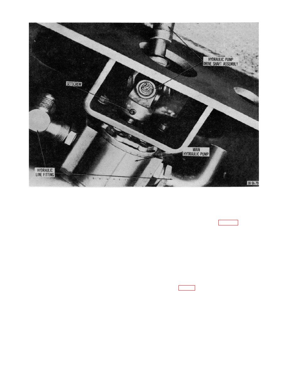 Figure 91. Main hydraulic pump and pump drive shaft assembly, installed on truck.
Remove bearing. Remove cross assembly
60. Hydraulic Control Valve Linkage
from end yoke.
a. Removal.
(8) Repeat procedure in (7) above to remove
(1) Remove floor panel and seat support.
two remaining bearings from cross
(2) Remove nut (1, fig. 93) that secures
assembly and shaft. Remove cross from
selector rod (2) to lever (3) and remove
shaft.
rod.
(9) Using procedures in (7) and (8) above,
(3) Remove two cotter pins from straight,
remove bearings from cross assembly
headed pins (4) and remove pins from links
located between slip joint and flange yoke.
and valve plungers.
Remove cross assembly.
(4) Remove capscrews (5) and lockwashers
b. Cleaning, Inspection, and Repair.
that secure selector lever bracket (11).
(1) Clean all parts except bearings in SD.
Remove bracket and hydraulic control
(2) Examine all parts for good condition, and
valve linkage.
replace damaged or badly worn parts.
b. Disassembly.
c. Assembly and Installation. Reverse procedures
(1) Remove remaining cotter pins (13 and 17,
in a above.
valve levers (8 and 22) and remove links.
109
|
|
Privacy Statement - Press Release - Copyright Information. - Contact Us |
