 |
|||
|
|
|||
|
Page Title:
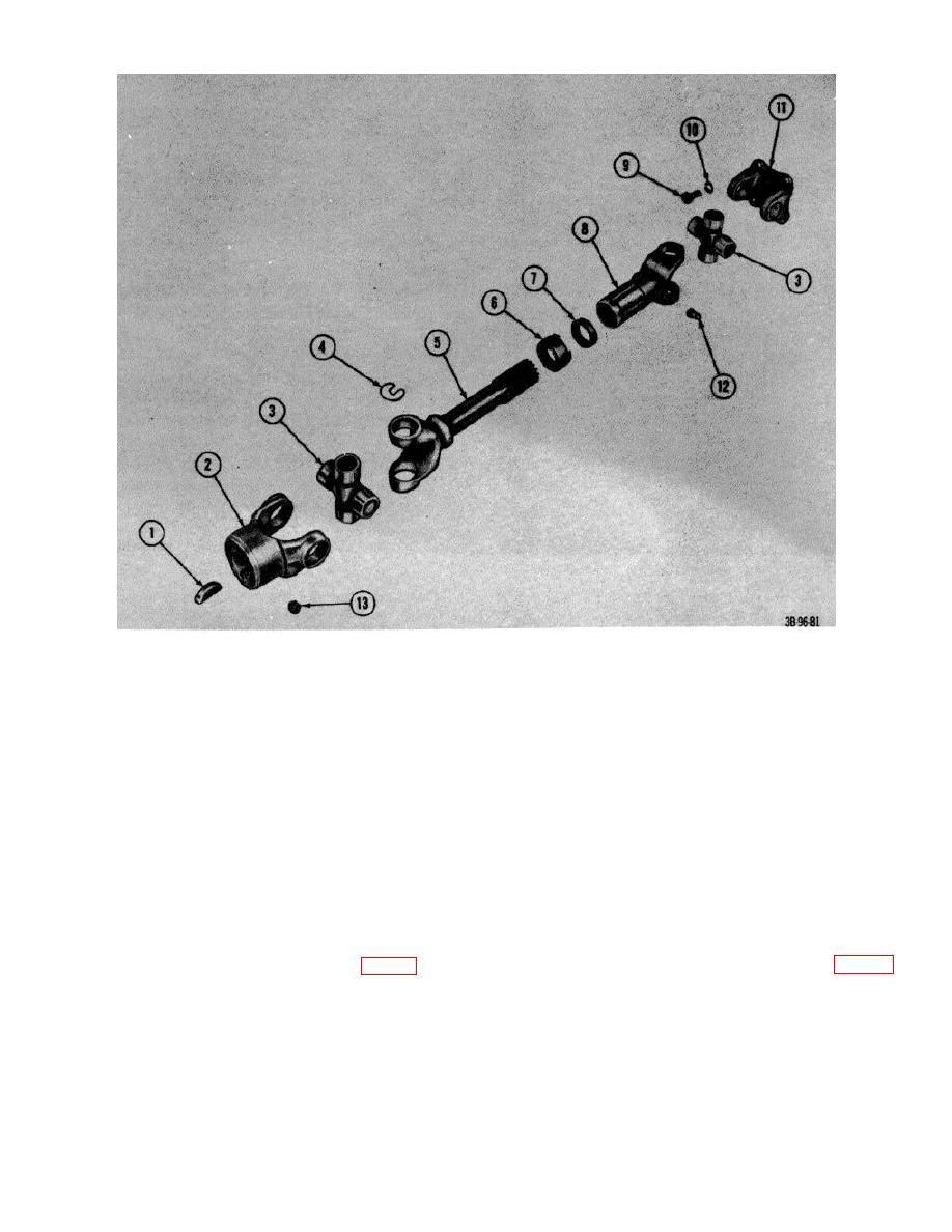
Figure 93. Hydraulic pump drive shaft assembly, exploded view. |
|
||
| ||||||||||
|
|
 1
Key
8
Joint, slip
2
Yoke, end
9
Bolt, machine
3
Cross assembly with bearings
10
Lockwasher
4
Clips, retaining
11
Yoke, flange
5
Shaft
12
Fitting, lubrication
6
Cap, dust
13
Setscrew
7
Gasket, cork
Figure 93. Hydraulic pump drive shaft assembly, exploded view.
mounting bolts (6) that secure hydraulic
61. Hydraulic Control Valve
control valve to valve mounting bracket
(9) and remove valve.
a. Removal.
(1) Remove floor panels and seat support.
b. Disassembly.
(2) Remove hydraulic control valve linkage
(1) Remove all line fittings from valve.
(par. 60).
(2) Place control valve in a vise, being
(3) Disconnect, cap, and mark all hydraulic
careful not to damage machined surfaces.
lines that connect to the control valve.
(3) Remove relief valve capnut (1, fig. 96)
(4) Remove bypass line fitting (7, fig. 94).
from adjusting screw (5).
(5) Remove the nuts, lockwashers and
AGO 7010A
111
|
|
Privacy Statement - Press Release - Copyright Information. - Contact Us |
