 |
|||
|
|
|||
|
Page Title:
Figure 94. Hydraulic control view and linkage, installed on truck. |
|
||
| ||||||||||
|
|
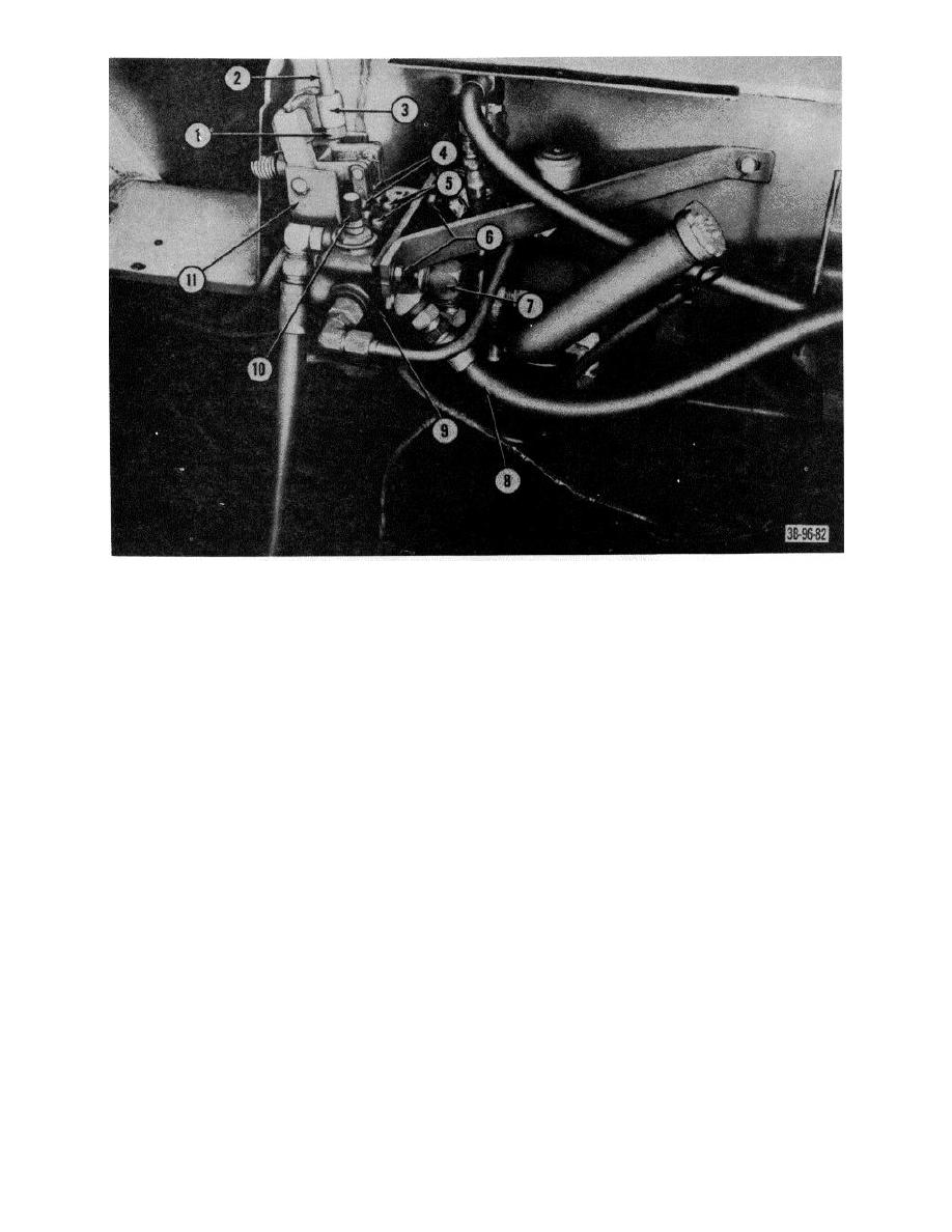 1
Nut
7
Fitting bypass line
2
Rod, selector
8
Hose, pump valve
3
Lever, selector
9
Bracket valve mounting
4
Pins, straight, headed
10
Setscrew, relief valve adjusting
5
Capscrews
11
Bracket, selector lever
6
Bolts, mounting
Figure 94. Hydraulic control view and linkage, installed on truck.
(4) Remove relief valve locknut (2) from
(10) Turn valve body, in the vise, so that
adjusting screw.
plungers (14 and 23) are in a horizontal
(5) Unscrew adjusting screw until loose.
position.
(6) Remove relief valve pilot plug (3) and
(11) Make certain that there are no burs or
preformed packing (4) from body (11).
sharp edges on the plunger eye that will
(7) Slide adjusting screw (5), relief valve
scratch or groove the honed plunger bore.
sleeve (8) and relief valve spring (9) from
(12) Mark the plungers for correct reassembly.
control valve body.
(13) Remove capscrews (22) that secure
(8) Unscrew and remove adjusting screw (5),
plunger caps (21) to valve body and
pilot spring (6) and relief valve poppet (7)
remove caps.
from relief valve sleeve (8).
(14) Pull plunger assemblies with wipers with
(9) Remove relief valve plug (13), shims, if
rings (15) and seal plates (16) from valve
any, and preformed packing (12) from
body.
valve body.
AGO 7010A
112
|
|
Privacy Statement - Press Release - Copyright Information. - Contact Us |
