 |
|||
|
|
|||
|
Page Title:
Cylinder Block, Cleaning, Inspection and Rpair |
|
||
| ||||||||||
|
|
 TM 10-3930-630-34
(3) Hone cylinders with a suitable honing tool
1-40.
Cylinder Block, Cleaning, Inspection and
to a good cross hatch honed pattern.
Repair
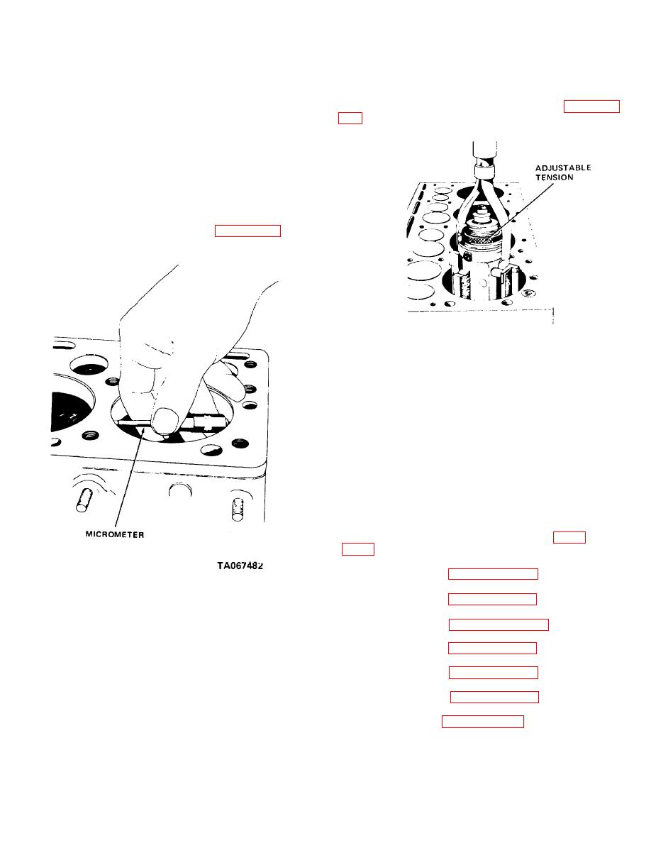
(4) Insert hone into cylinder and expand to
a. Clean all oil passages with cleaning solvent
cylinder wall with a slight tension as shown in figure 11-
Fed. Spec. P-D-680) and blow out with compressed
air.
b. Clean valve compartment and cylinders
thoroughly.
Remove carbon deposits from top of
crankcase and cylinder walls. Do not nick or scratch
surfaces.
salve area and bearing flanges.
(1) Measure original bore diameter above ring
travel with a micrometer as shown on figure 11-42, at 45
degree intervals.
TA067483
Figure 11-43. Honing cylinders
(5) Use a clean brush and wet cylinder walls
and stones with kerosene. Use a hand drill and surface
one cylinder with an up and down motion. Apply
kerosene as needed occasionally while honing.
Increase tension until a good finish is obtained. A
smooth finish of 10 to 15 micro inches is desired.
(6) Remove hone. Clean bores with a clean
rag soaked in oil (OE/HDO). Wipe bore clean with a
clean dry cloth. Measure bores with a micrometer to
see that they are within tolerances specified above.
11-41. Cylinder Block, Reassembly and Installation
a. Reassembly. Reassemble the cylinder block in
reverse numerical sequence as illustrated in figure
b. Installation.
(1) Refer to paragraph 11-26 and install the
camshaft.
Figure 11-42. Measuring cylinder bore diameter.
(2) Refer to paragraph 11-37 and install the
crankshaft and main bearings.
(2) Measure the bore diameter below the top
(3) Refer to para, graph 11-33 and install the
of ring travel in the same manner.
flywheel housing.
(3) If the difference between the two
(4) Refer to paragraph 11-30 and install the
measurements does not exceed 0.008 inch (0.202 mm),
flywheel.
the engine does not have to be rebored.
(5) Refer to paragraph 11-23 and install the
(4) If the difference exceeds 0.008 inch,
gear cover and fan drive.
rebore the cylinder.
(6) Refer to paragraph 11-19 and install the
e. Repair cylinder as follows:
piston and connecting rods.
(1) Ridge ream the cylinder to remove the
(7) Refer to paragraph 11-15 and install the oil
unworn area at the top.
pressure relief valve.
(2) Rebore cylinder diameter to a maximum of
3.1268 inches (79.42-mm). This diameter will allow a
0.002 inch (0.050-mm) excess to allow for honing the
cylinder walls.
11-29
|
|
Privacy Statement - Press Release - Copyright Information. - Contact Us |
