 |
|||
|
|
|||
|
Page Title:
Section V. FLYWHEEL AND FLYWHEEL HOUSING |
|
||
| ||||||||||
|
|
 TM 10-3930-630-34
Section V. FLYWHEEL AND FLYWHEEL HOUSING
11-27. Description
a. The flywheel is mounted on the rear end of the
crankshaft. The ring gear is mounted around the
flywheel and meshes with the starter gear to start the
engine.
b. Timing decals are mounted on the flywheel to
aid in timing the engine.
11-28. Flywheel, Removal and Disassembly
transmission and torque converter.
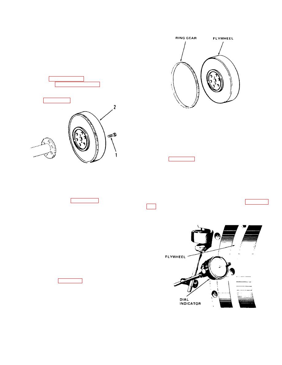
c. Remove the flywheel in numerical sequence as
illustrated on figure 11-31.
TA067472
Figure 11-32. Flywheel ring gear, removal and
installation.
11-30. Flywheel, Reassembly and Installation
a. Install two guide studs (3/8 - 24 x 4 inches long)
in crankshaft flange and install flywheel on studs. Install
screws (1, fig. 11-31) and tighten screws to a torque of
35 to 40 foot-pounds (47.4 to 54.2 N ). Remove guide
m
TA067471
studs an(d install remaining screws.
1. Screw
2. Flywheel
b. Check flywheel as follows:
(1) Mount a dial indicator as shown in figure
Figure 11-31. Flywheel, removal and installation.
11-33. Set indicator to contact vertical surface of
flywheel. Maximum indicator reading must not exceed
11-29. Flywheel, Cleaning, Inspection and Repair
0.008 inch (0.203 min).
(2) Mount dial indicator- as shown in figure 11-
and damage. If ring gear is damaged, remove ring gear
as follows:
reading must not exceed 0.008 inch (0.203 mm).
(1) Grind a notch in ring gear at root of one of
the teeth.
(2) Heat gear to 475F (246C) to expand
gear. Pry gear from flywheel.
b. Clean all metal 1)arts in cleaning compound,
solvent (Fed. Spec. P-D-680) and dry thoroughly.
c. Inspect mounting surface of flywheel for burs
and nicks. Remove burs and nicks with fine emery
cloth.
d. Inspect mounting holes and crankshaft flange
for elongation and damage.
e. Replace unserviceable parts.
gear to 475F (246C). Start ring gear on flywheel with
chamfered ends of teeth set to engage starter gear.
Drive ring gear down tight against the shoulder on
flywheel. Let ring gear cool slowly.
TA067473
Figure 11-33. Checking flywheel run-out.
11-22
|
|
Privacy Statement - Press Release - Copyright Information. - Contact Us |
