 |
|||
|
|
|||
|
Page Title:
Gear Cover and Fan Drive, Reassembly and Installation |
|
||
| ||||||||||
|
|
 TM 10-3930-630-34
11-23. Gear Cover and Fan Drive, Reassembly and
NOTE
Installation
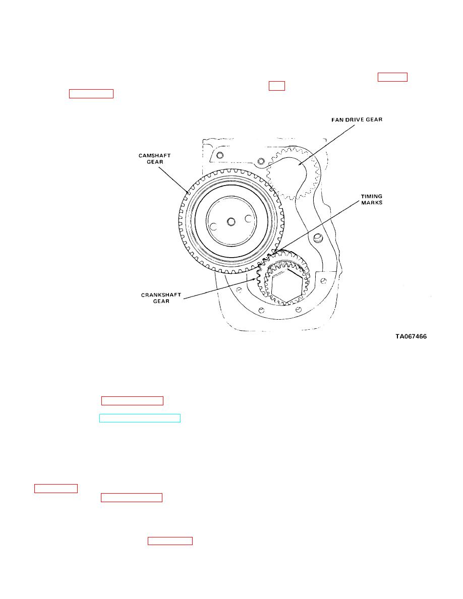
Make sure the marked teeth on the
camshaft gear straddle the marked
a. Reassembly. Reassemble the gear cover and
tooth on the crankshaft gear (fig. 11-
fan drive in reverse order of numerical sequence as
illustrated in figure 11-25.
Figure 11-26. Gear train and timing works.
b. Installation.
11-25. Camshaft, Cleaning, Inspection and Repair
(1) The gear cover and fan drive is installed
a. Clean all metal parts in cleaning solvent (Fed.
during the reassembly procedure.
Spec. P-D-680) and dry thoroughly.
(2) Refer to paragraph 2-14 and install the
b. Inspect camshaft for damage and wear to lobes
hydraulic pump.
and bearing journals.
(3) Refer to TM 10-3930-630-12 and install
c. Check oil pump gear teeth on camshaft for wear
belts, fan and radiator on engine.
and damage.
d. Check camshaft as follows:
11-24. Camshaft, Removal and Disassembly
(1) Measure front bearing journal diameter.
a. Removal.
Diameter must be 1.8725 to 1.8715 inches (47.7 to
(1) Correct timing is critical to proper engine
47.53 mm). Minimum wear diameter is 1.8705 inches
operation. It is accomplished by meshing the camshaft
(47.51 mm).
drive gear with crankshaft gear timing marks as shown
(2) Center bearing journal diameter should be
1.7465 to 1.7455 inches (44.36 to 44.33 mm). Minimum
(2) Refer to paragraph 11-21 and remove the
wear diameter is 1.7444 inches (44.30 mm).
gear cover and fan drive.
(3) Rear bearing journal diameter should be
(3) The camshaft is removed in the
1.2475 to 1.2465 inches (31.68 to 31.66 mm). Minimum
disassembly procedure.
wear diameter is 1.7444 inches (44.30 mm).
b. Disassembly. Disassemble the camshaft in
numerical sequence as illustrated in figure 11-27.
11-19
|
|
Privacy Statement - Press Release - Copyright Information. - Contact Us |
