 |
|||
|
|
|||
|
|
|||
| ||||||||||
|
|
 shaft, paragraph 3-13c, and camshaft, paragraph 3-14
3-14. Camshaft and Bearings
a.
a. Removal.
b. Cleaning, Inspection and Repair. Follow procedure
(1) Remove the engine from the truck (para 2-6
in step a. above and then proceed as follows:
a)
(1) Remove gasket residue from cylinder block.
(2) Remove the distributor from the engine.
(2) Remove dirt, carbon and sludge.
(3) Remove valves and tappets. (para 3-5 a.)
(3) Remove plugs and clean oil and water
(4) Remove oil pump. (para 3-10 a.).
passages.
(5) Remove timing gear cover and related parts.
(4) Clean block with steam or a vapor degreaser
(para 3-7 a)
and dry with compressed air.
(6) Remove fuel pump.
(5) Inspect block for cracks or damage.
(7) Using a puller, remove the cam and crank
(6) Inspect expansion plugs for good condition
and tight seal, and replace plug if necessary.
(8) Remove camshaft thrust plate (2, fig. 3-1).
(7) Examine machined surfaces for scratches,
(9) Use a feeler gage to check the clearance
nicks, burrs or similar damage.
between the camshaft (1) journals and the camshaft
(8) Examine all threaded holes and retap any that
bushings (8, 9, and 10). Correct clearance is 0.002 to
are stripped or damaged.
0.004 inch for all bushings. Replace all camshaft
(9) Install new studs when old ones are bent or
bushings if clearance of any exceeds this clearance.
found with damaged threads.
(10) Remove camshaft through front of engine
(10) Inspect cylinder bores while holding a light at
block, being careful not to damage lobes or camshaft
the bottom of each bore. If rust pits are evident, or if
bushings.
bores are deeply scratched or scored, send block to
(11) Remove flywheel and flywheel housing from
depot for reboring.
engine, and remove expansion plug from rear of engine
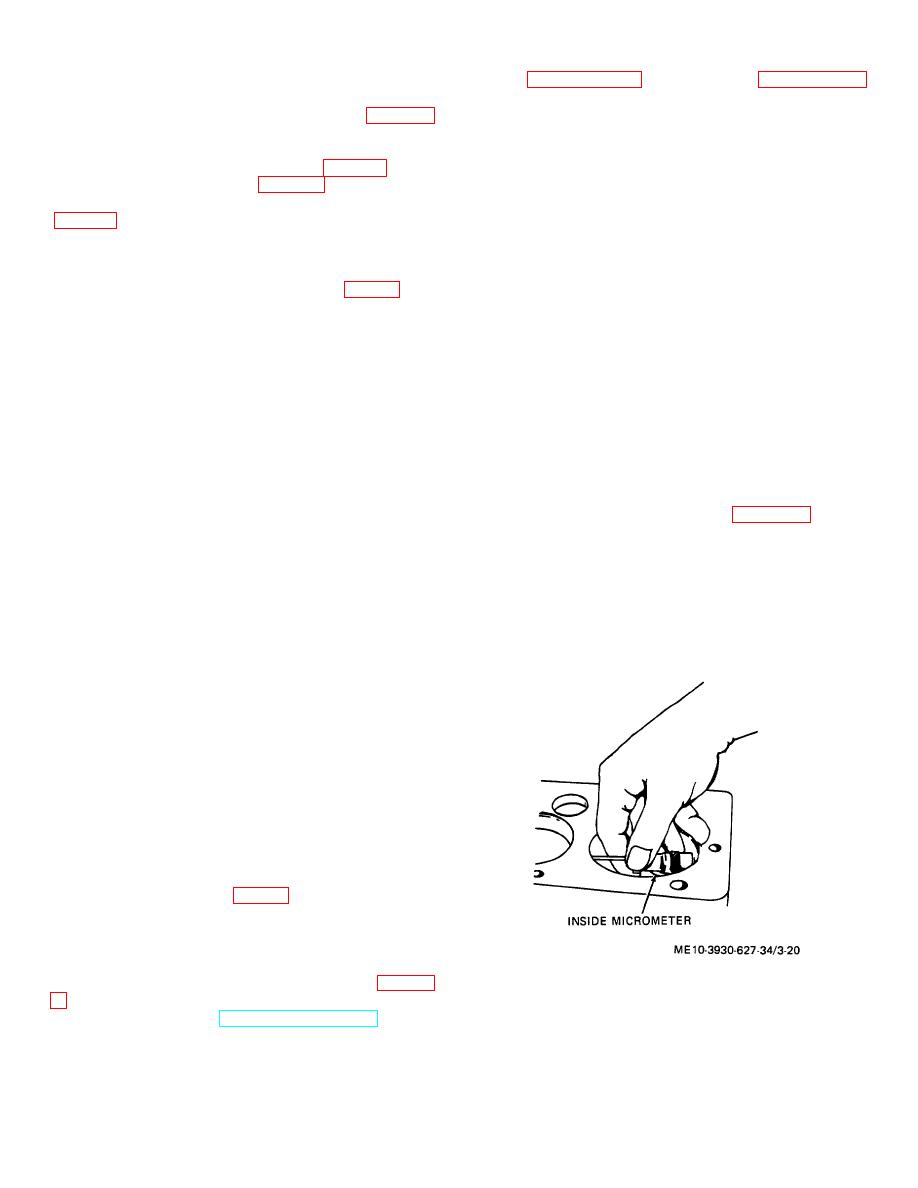
(11) Rotate dial indicator in cylinder or measure
in order to gain access to rear camshaft bushing if it
bore with inside micrometer, and observe and record
must be replaced.
largest and smallest indications (fig. 3-20).
The
(12) Remove camshaft bushings from engine
difference between the indications is the amount of out-
block with driver.
of-round. Move dial indicator or micrometer up and
b. Cleaning, Inspection and Repair.
down in cylinder and note largest and smallest
(1) Clean all metal parts in solvent and dry
indications. The difference between indications is the
thoroughly.
amount of taper of the cylinder. If out-of-round or taper
(2) Inspect camshaft journals and lobes for wear,
exceeds 0.004 inch or if overall wear exceeds 0.008
breaks, rough spots and other damage. Camshaft must
inch, have a depot facility rebore cylinder walls and
be replaced if lobes or journals are damaged.
install oversize pistons and rings.
(3) Measure camshaft journals with a micrometer.
Specified journal diameters are as follows: front, 1.8715
to 1.8725 inches; center 1.7455 to 1.7465 inches; rear,
1.2465 to 1.2475 inches. The wear limit on all journals
is 0.002 inch less than minimum original size.
(4) Replace defective parts.
c. Installation.
(1) Apply a light coat of oil to bushings and install
them in engine block.
New bushings require no
reaming, only care in installation. Line up oil holes in
bushings with oil passages in block.
(2) Install thrust plate and check camshaft end
play. It should be between 0.005 and 0.009 inch.
(3) Install the timing gears, being careful to line
up the marks on the gears (fig. 3-6).
(4) Complete installation by reversing necessary
procedure in step a. above.
3-15. Cylinder Block
Figure 3-20. Measuring cylinder bore.
remaining accessories, (TM 10-3930-627-12,) crank-
3-15
|
|
Privacy Statement - Press Release - Copyright Information. - Contact Us |
