 |
|||
|
|
|||
|
|
|||
| ||||||||||
|
|
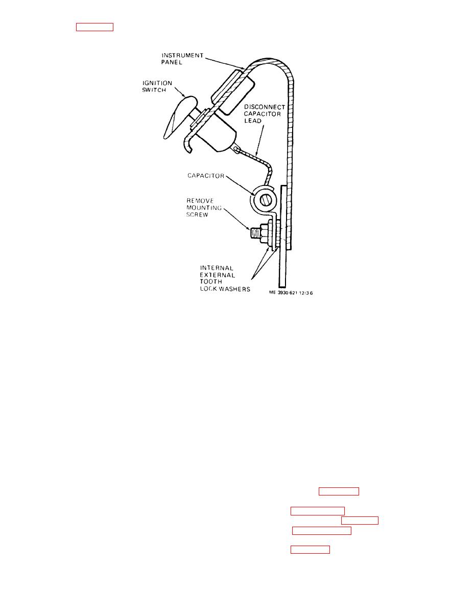 capacitor.
Figure 3-6. Ignition switch capcitor, removal and installation.
3-22. Testing of Suppression Components
ence is indicated, isolate the cause of interference by
the trial-and-error method. Replace the capacitors in
a. Test capacitors for leaks and shorts on a capaci-
turn until the cause of interference is located and
tor tester. Replace defective capacitors.
eliminated.
b. If test equipment is not available and interfer-
Section VIII. ENGINE ASSEMBLY
3-23. General
3-24. Cylinder Head
a. Removal. Remove the cylinder head as follows:
a. The engine is a Waukesha Model FCB-G5943
(1) Drain radiator (para 3-37) to lower water
gasoline engine. It is a four cylinder, four stroke cy-
level below cylinder head.
cle, flat head engine. The engine is mounted on the
(2) Refer to paragraph 3-37 and remove the ther-
frame below and behind the operator's seat. The fol-
mostat housing and thermostat (para 3-38).
lowing paragraphs describe engine maintenance
(3) Refer to paragraph 3-46 and remove spark
procedures allocated to organizational maintenance.
plugs and ignition cables.
Note. To gain access to engine compartment to perform the
(4) Refer to figure 3-7 and remove the cylinder
maintenance, remove seat and side panels as necessary.
3-12
|
|
Privacy Statement - Press Release - Copyright Information. - Contact Us |
