 |
|||
|
|
|||
|
Page Title:
Figure 3-7. Cylinder head, exploded view. |
|
||
| ||||||||||
|
|
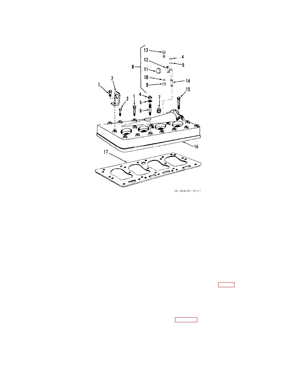 nuts (4) and lock washers (5).
head and gasket as follows:
(6) Remove cylinder head (16) and gasket (17).
(5) Remove one bolt (1) and lifting eye (2). Re-
move 10 bolts (3) and two bolts (15). Remove two
1. Bolt
10. Lock washer
2. Lifting eye
11. Support block
3. Bolt
12. Cable support
4. Nut
13. Screw
5. Lock washer
14. Stud
6. Stud
15. Bolt
16. Cylinder head
7. Pipe plug
17. Cylinder head gasket
8. Cable support assembly
9. N u t
Figure 3-7. Cylinder head, exploded view.
c. Installation.
b. Cleaning and Inspection.
(1) Install new gasket (17, fig. 3-7) on engine block
(1) Clean all carbon from combustion areas on
and install cylinder head. Secure cylinder head (16),
cylinder head and engine block. Scrape carbon from
cable support (8), and lifting eye (2) and secure with
surfaces with a scraper or wire brush.
bolts (1,3, and 15), nuts (4), and lock washers (5).
(2) Clean cylinder head with cleaning compound,
(2) Tighten cylinder head bolts and nuts to a
solvent (Spec. P-S-661) and dry thoroughly.
torque of 61 to 62 foot pounds, in the sequence
(3) Clean all gasket surfaces on cylinder head and
shown on figure 3-8.
block and inspect for nicks or cracks which could
cause leaks. Check surfaces with a straightedge for
warpage.
3-13
|
|
Privacy Statement - Press Release - Copyright Information. - Contact Us |
