 |
|||
|
|
|||
|
Page Title:
Section VII. RADIO INTERFERENCE SUPPRESSION |
|
||
| ||||||||||
|
|
 Section VII. RADIO INTERFERENCE SUPPRESSION
d. The following ground and mounting parts utilize
3-19. General Methods to Obtain Proper
internal-external teeth lockwashers to provide posi-
Suppression
tive grounding.
Essentially, suppression is obtained by providing a
(1) Alternator mounting bolt.
low resistance path to ground for stray currents. The
(2) Battery ground strap at transmission.
methods used include grounding the frame with
(3) Regulator mounting screws.
bonding straps, and using capacitors and resistors.
(4) All capacitor mountings.
e. Spark plugs are the resistor type.
3-20. Interference Suppression Components
f. Spark plug and ignition coil leads and cables are
non-metallic conductor type.
a. A ground strap is connected between the instru-
ment panel and the frame.
3-21. Replacement of Suppression
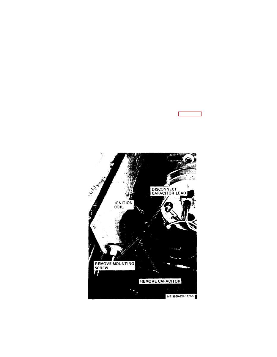
b. The ignition coil is suppressed by the use of a
Components
0.25 MFD capacitor mounted with the coil mounting
a. The following paragraphs detail methods to re-
screw.
place suppression components.
c. The ignition switch is suppressed with an 0.25
MFD capacitor mounted on the underside of the in-
capacitor.
strument panel.
Figure 3-5. Ignition coil capacitor, removal and installation.
3-11
|
|
Privacy Statement - Press Release - Copyright Information. - Contact Us |
