 |
|||
|
|
|||
|
Page Title:
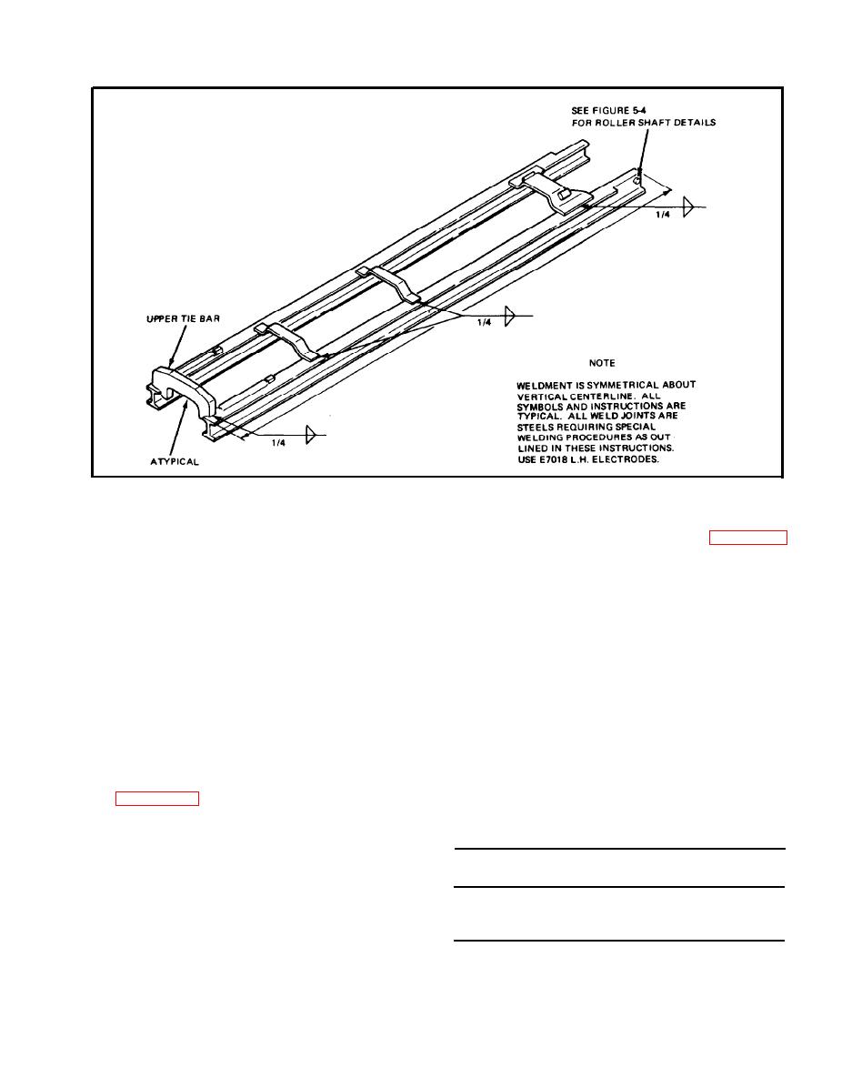
Figure 5-5. Welding Repair of Inner Rail Assembly |
|
||
| ||||||||||
|
|
 Figure 5-5. Welding Repair of Inner Rail Assembly
for chill cracks. If any, prepare as in paragraph
joints. It will be obvious that the selection of
5-19 (above) and reweld.
electrode sizes under 5/32" is unwise for this
application.
b. Joint inspection is recommended by either of
the following methods:
f. All joints calling for 3/8" (or more) fillet must
be made in 2 or more passes. Bead from first pass is
1. Dye penetrant, wet or dry process.
t o be chipped and work must not be allowed to
cool between passes.
2. Magnetic particle inspection. Manufacturer's
instructions included with the testing gear should
g. Welding on fork assemblies or upright
be followed as applied to the size, shape, or other
m e m b e r s usually involves material with up to
nature of the work being tested. In general,
0.45% Carbon. Two-pass welding with slag removal
however, the conditions shown below will serve in
between passes allows one pass to act as additional
most cases, whether the process employs direct or
preheat or post heat to the other pass. The
rectified current.
heat-affected zone hardness will be kept low and
safe in this manner.
(a) Distance between prods shall not be less
than 2 inches.
h. Figures 5-1 thru 5-5 illustrate points of weld
and proper weld symbols for the types of weld to
( b ) Ratio for prod spacing/amperage/section
be used in each case when welding on carriage and
thickness:
upright parts.
Thickness
Thickness
5-21. INSPECTION.
Under 3/4"
over 3/4"
Spacing
2 " to 4 "
2 0 0 - 3 0 0 amps
a. Remove slag and spatter, and check for
3 0 0 - 4 0 0 amps
4 " to 6 "
3 0 0 - 4 0 0 amps
c o n f o r m i t y to paragraph 5-20 (above). Finished
400-600 amps
6 " to 8 "
400-600 amps
and cooled joints should be thoroughly inspected
600-800 amps
5-11
|
|
Privacy Statement - Press Release - Copyright Information. - Contact Us |