 |
|||
|
|
|||
|
Page Title:
Figure 4-32. Brake System Bleed Points |
|
||
| ||||||||||
|
|
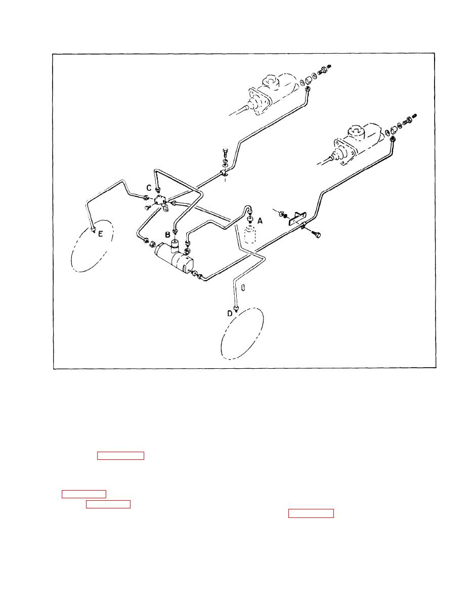 Figure 4-32. Brake System Bleed Points
the flow. Tighten fittings securely when all air is
d . Place a flat pan under the axle adapter to
expelled.
catch brake fluid spillage, and connect the pressure
bleeder line to the brake master cylinder. Open the
pressure bleeder valve.
g. When bleeding wheel cylinders (bleed points D
and E), attach a small hose to the bleeder screw on
e. Refer to figure 4-32 for identification of the
the axle adapter, submerge the other end of the
various bleed points within the brake system.
hose into a jar of clean brake fluid. Hold the jar at
a point higher than the bleeder screw, and open the
f. With the bleeder hook-up completed as shown
bleeder screw, allowing fluid to flow into the jar
in figure 4-33, open bleed points B and C (fittings
until no more bubbles can be seen in the flow as
shown in figure 4-34) and allow fluid to flow from
shown in figure 4-35.
loosened fittings until no further bubbles appear in
4-23
|
|
Privacy Statement - Press Release - Copyright Information. - Contact Us |
