 |
|||
|
|
|||
|
|
|||
| ||||||||||
|
|
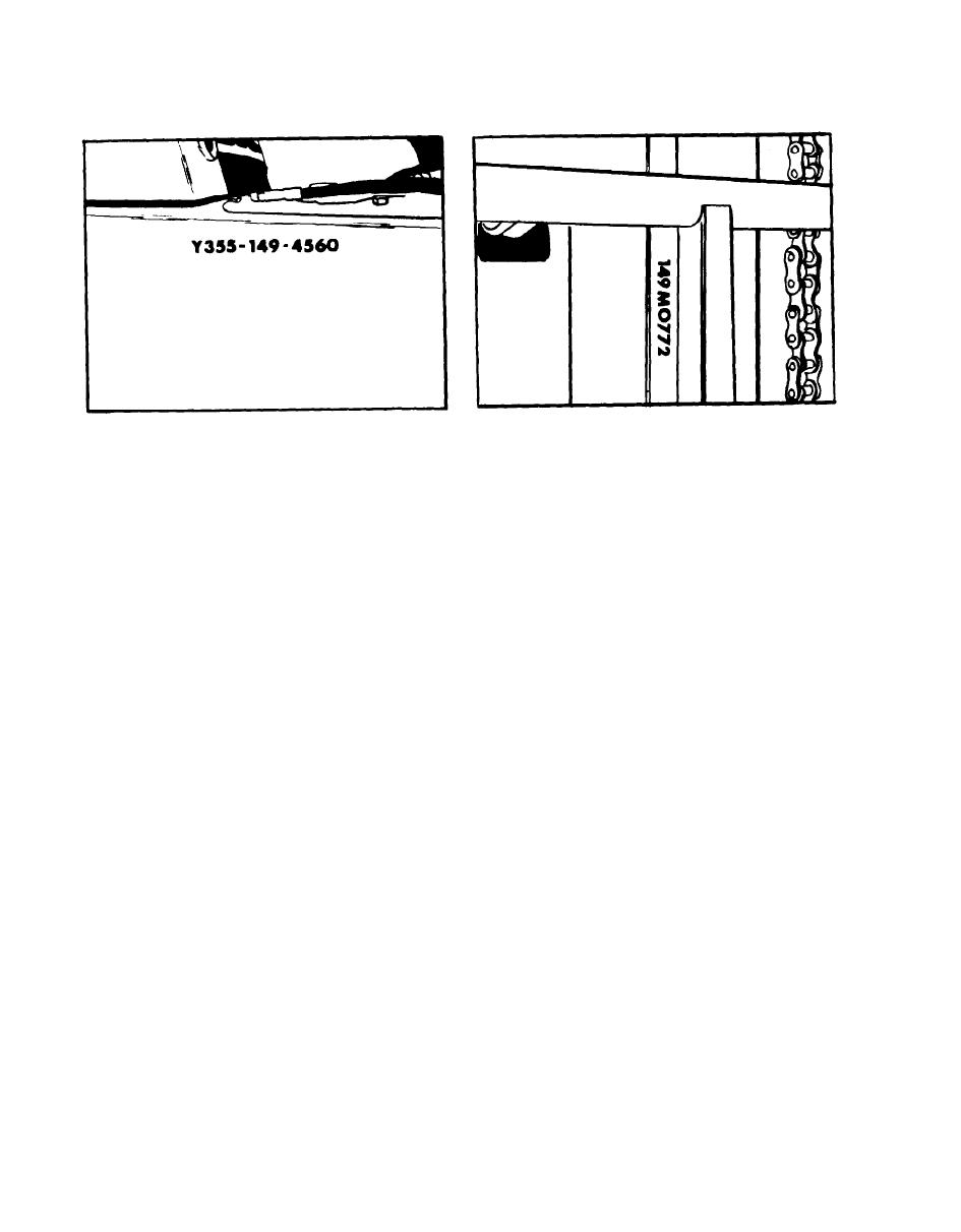
 Upright Deck Number
Figure 1-9.
Serial Number Location
Figure 1-8.
Location
stationary tube
is bolted to the
The first stage uses chains which have
lower mounting bracket of the mast
one end attached to the lift cylinder
assembly.
The purpose of the lift
chain anchor. The other end is
cylinder is to supply the power to
attached to the lifting carriage. As
hoist and hold the cargo load.
The
the first stage piston extends. It
control lever for operating the lift
At the
pulls the carriage upward.
cylinder is on the cowl to the left
upper extreme of the stroke, the pis-
of the tilt control lever.
Lowering
ton bottoms against a spacer stopping
rate of the mast assembly is regulated
the piston and diverting the oil to
by movement of the control valve
In the second
the inner piston rod.
lever and lift cylinder flow control
the outer barrel,
stage of the lift,
valve and is in no way affected by
intermediate rod, and stationary rod
the engine speed.
are forced upward on the inner rod,
moving the inner rails and carriage
1-45.
TILT CYLINDERS.
The two tilt
The carriage, inner and
upward.
cylinders are located on each side of
outer tracks of the upright assembly
the vehicle below the operator's
have rollers for ease of movement.
floor plates. The purpose of the tilt
The carriage upper fork bar is
cylinders is to tilt the mast assembly
notched to permit forks to be moved
forward or backward.
The control lever
horizontally on the upper bar to
for operating these cylinders is on the
obtain varying distances between
cowl to the right of the operator.
To move fork horizontally,
forks.
lift lever on top of fork and slide
1-46.
OVERHEAD GUARD. The overhead
in direction desired.
guard meets the ANS B56.1 Safety
Standard for Powered Industrial Trucks
LIFT CYLINDER. The telescopic
1-44.
and has been subjected to an impact
lift cylinder is mounted in a vertical
test load of 16,000 foot pounds.
The
position between the masts on the front
overhead guard should remain installed
of the vehicle. The intermediate
on the truck at all times during opera-
piston rod of the cylinder is bolted
tion.
With the upright completely
to the lifting chain sheave carriage
collapsed the overall height of the truck
at the top. The cylinder innner
with overhead guard will operate in a
84 inch door opening.
1-20
|
|
Privacy Statement - Press Release - Copyright Information. - Contact Us |