 |
|||
|
|
|||
|
Page Title:
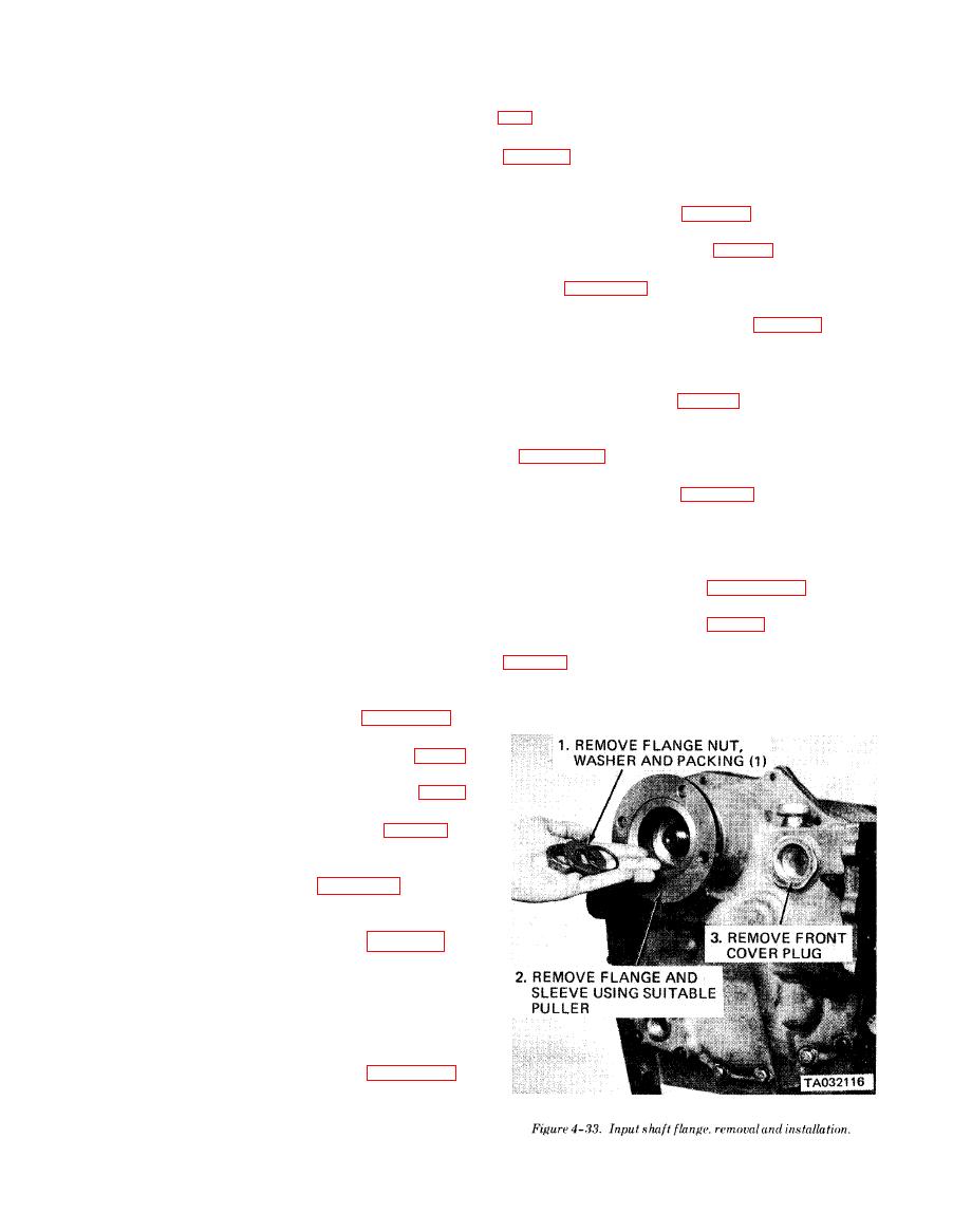
Figure 4-33.Input shaft flange, removal and installation |
|
||
| ||||||||||
|
|
 TM 10-3930-634.34
(13) Install oil seal (21) in housing (7), and start
bearing cap in reverse of instructions shown in figure
shift rail (13) into the housing with detent notches fac-
ing down. Through opening in top of housing insert de-
(30) Install idler shaft nut on end of idler shaft
tent spring (15) and ball (14). Depress the ball and
push the shift rail over the ball.
250-300 lb-ft torque.
(14) Assemble shift fork (18) and shift hub (17)
(31) Install new gasket on idler bearing cap.
with longest hubs of each facing in opposite directions.
Install idler bearing cap (fig. 4-37, A) and torque
Position assembly in disconnect housing (7), shift fork
screws to 24 lb-ft.
long hub facing the front, and install on end of shift
(32) Install parking brake (para 4-8).
rail (13). Aline setscrew hole in shift fork hub with
(33) Install the forward and second clutch as
dimple on the shift rail. Install setscrew (12) and
shown in figure 4-36, carefully engaging splines of in-
lockwire. Pull shift rail out as far as possible.
ner clutch discs with splines of second gear.
(15) Install inner retaining ring (19) in disconnect
( 3 4 ) Install input shaft (1, fig. 4-45) with
housing.
associated parts (1 through 7) in front cover (21) in
(16) Press bearing (20) onto disconnect shaft (16);
reverse of numerical sequence shown.
insert assembly into disconnect housing, engaging
(35) Install forward clutch front bearing retaining
large splines of shaft with shift hub (17). Install outer
ring in rear of front cover (fig. 4-34, C).
retaining ring (19).
(36) Install new gasket on face of transmission
(17) Press new seal (10) into disconnect housing
case and install front cover in reverse of instructions
(7). Seat the seal flush to 1/16 inch below the front face
in figure 4-34. Tighten capscrews to 39 lb-ft torque.
NOTE
of housing.
(18) Install cup plug (11) in the disconnect hous-
Retaining ring ears (fig. 4-34), must be
ing (7).
spread completely when installing front cov-
(19) Install a new preformed packing (8) on the
er, then released to engage groove in front
disconnect housing (7).
bearing of forward and second clutch.
(20) Install assembled disconnect assembly using
(37) Install front cover plug, and flange and sleeve
shims (9), selected in (12) above. Install screws (5) and
in reverse of instructions in figure 4-33. Tighten
washers (6). Tighten screws to 86 lb-ft of torque.
flange nut to 175-200 lb-ft torque.
(21) Install output flange (4), preformed packing
(38) Install control valve (para 4-7).
(3), flat washer (2) and flange nut (1). Block output
w. Installation. Install the transmission assembly
gear (29) and tighten nut (1) for 200 to 250 lb-ft of
torque.
(22) Install low clutch assembly in rear of trans-
mission case in reverse of instructions in figure 4-41.
(23) Install reverse and third speed clutch and low
speed drive gear in reverse of instructions in figure
4-40.
(24) Install fourth speed clutch as shown in figure
4-39.
(25) Install low clutch rear bearing (fig. 4-59),
with retaining ring groove to the rear.
(26) Position new gasket on transmission case and
install rear cover as instructed in figure 4-60.
NOTE
Be sure lock ball is in place and positioned
properly to receive the rear cover (fig. 4-60,
A).
(27) From front of transmission case, tap low
c l u t c h and idler shaft to rear, using a rawhide
hammer, to allow clearance to install rear bearing
retaining rings.
(28) Install low clutch and idler shaft bearing
locating rings in reverse of instructions in figure 4-37,
B and C.
(29) Install two piston rings on low clutch shaft.
Install new gasket and packing and install low shaft
|
|
Privacy Statement - Press Release - Copyright Information. - Contact Us |