 |
|||
|
|
|||
|
|
|||
| ||||||||||
|
|
 TM 10-3930-634-34
(9) Attach air line to water hole cover plate and
used immediately, spray machined surfaces with
apply 80-100 PSI air pressure to water jackets and ob-
OE-10 engine oil. If cylinder block is to be stored for
serve water in tank for bubbles which will indicate
an extended period of time, spray or dip block in a
cracks or leaks.
polar-type rust preventive compound.
(10) Remove block from water tank. Remove
g. Reassembly. Reassemble the cylinder block in re-
plates, seals, and gaskets and blow out all passages in
verse of numerical sequence as shown in figure 3-147.
h. Installation.
block with compressed air.
f. Inspection and Repair.
(1) Install all components and subassemblies (par
(1) Check top machined surfaces of block for flat-
3-2 through 3-38).
ness with an accurate straight edge and a feeler gage.
(2) Install engine (para 2-5).
Surfaces must not vary more than 0.003 inch trans-
versely, and not over 0.006 inch longitudinally.
(2) Make sure seal ring grooves are thoroughly
clean. Inspect grooves and lands for evidence of pitting
and erosion. If both grooves are eroded to extent that
sealing is affected, block must be replaced.
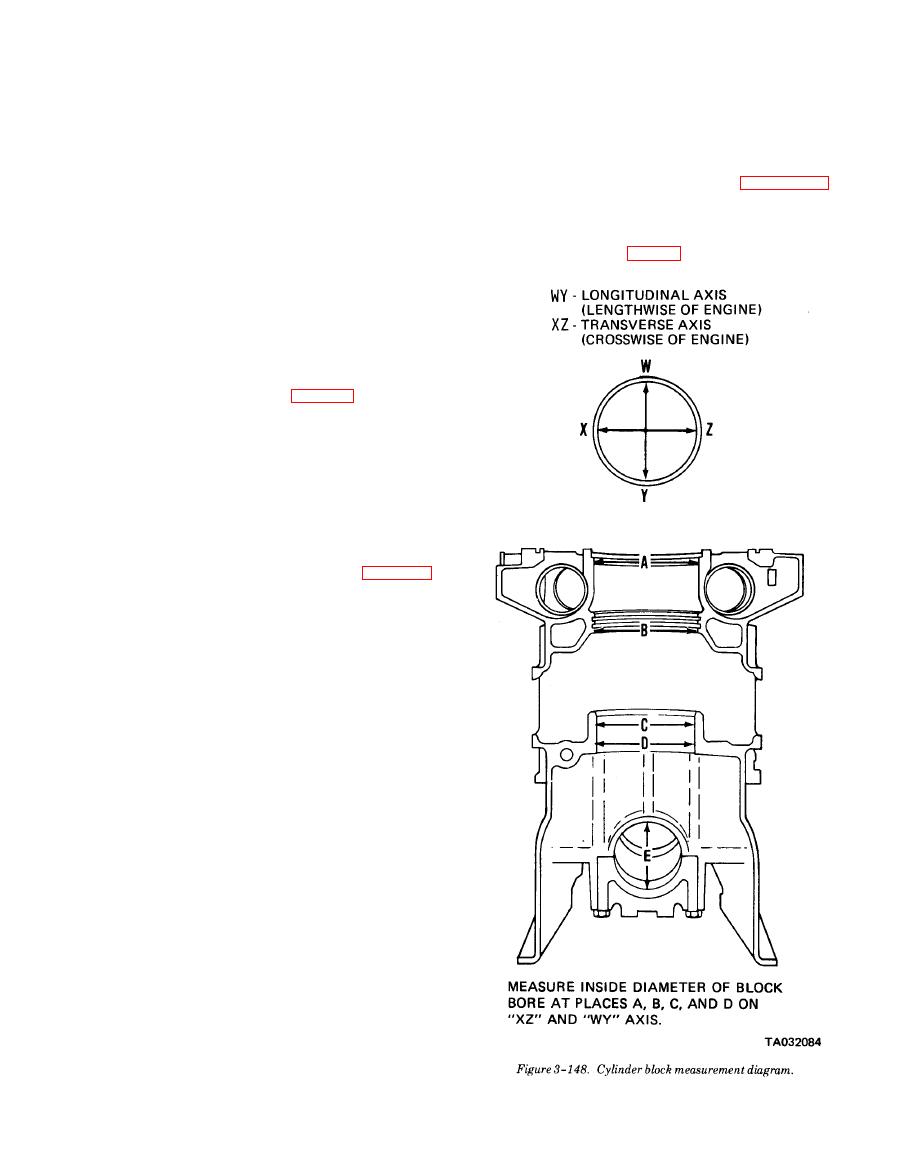
(3) Measure each cylinder block cylinder bore at
positions on axes 90 degrees apart (fig. 3-148). If di-
ameter does not exceed 4.5235 inches at position "A",
4.4900 inches at position "B" (and a sealing problem
has not occurred), or 4.3595 inches at position "C" and
"D", block may be reused. Taper and out-of-round must
not exceed 0.0015 inch.
(4) Lubricate threads and underside of each 9/16-12
main bearing cap bolt head with OE-30 engine oil. In-
stall four main bearing bolts with temporary spacers,
and tighten bolts to 120-130 lb-ft torque.
(5) Measure main bearing bores (E, fig. 3-148).
Bearing bores must be 3.251 to 3.252 inches. If bores
do not fall within these limits, discard block.
(6) Check main bearing bores for alinement. Bear-
ing bores may be considered properly alined with one
another if a crankshaft with standard size journals can
be rotated freely by hand, after new main bearing
shells have been installed and lubricated, and bearing
caps have been secured.
(7) Make sure cylinder liner counterbores in block
are clean. Check counterbore depth. Depth must be
from 0.300 inch to 0.302 inch and must not vary more
than 0.0015 inch throughout entire circumference.
Counterbored surfaces must be smooth and square
with cylinder bore within 0.001 inch total indicator
reading. There must not be over .0001 inch difference
in depth between any two adjacent cylinder counter-
bores when measured along the longitudinal center
line of the cylinder block.
(8) Check all machined surfaces and threaded
holes in block. Remove nicks and burrs from machined
surfaces with a fine mill file. Clean up damaged
threads in tapped holes with proper tap or install
helical thread inserts if threads cannot be cleaned up.
(9) If a new service replacement block is used,
stamp unit serial number and model number on top
right hand corner of new block. Make sure bearing
caps are properly numbered.
(10) After inspection, if cylinder block is not to be
|
|
Privacy Statement - Press Release - Copyright Information. - Contact Us |