 |
|||
|
|
|||
|
Page Title:
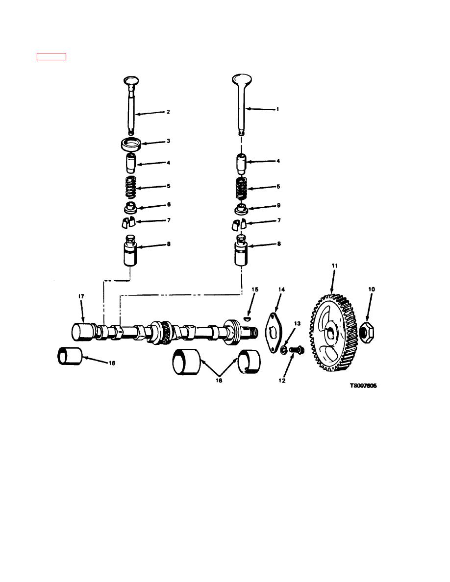
Figure 9-6. Valves and Camshaft, Exploded View. |
|
||
| ||||||||||
|
|
 TM 10-3930-632-34
c. Using a spring lifter, compress the valve spring
position. Rotate the engine crankshaft to close the
remaining valves and remove the remaining locks.
(5, fig. 9-6) at each valve (1I and 2) and remove the
valve locks (7) from each valve that is in the closed
10.
Hex nut
1.
Intake valve
11.
Timing gear
2.
Exhaust valve
12.
Bolt
3.
Exhaust valve seat
13.
Lockwasher
4.
Valve guide
14.
Thrust plate
5.
Valve spring
15.
Woodruff key
6.
Spring seat
16.
Bearing set
7.
Valve lock
17.
Camshaft
8.
Valve tappet
9.
Spring seat
Figure 9-6. Valves and Camshaft, Exploded View.
d.
Lift each valve from the top of the block. Place
valve springs (5). Remove the valve tappet assemblies
(8).
them in order in a rack to assure that each will be
f.
Do not remove the valve guides (4) or valve
reassembled in the same valve guide from which it was
seat inserts (3) unless inspection indicates that they are
removed.
e.
Remove the valve spring retainer seats (6) and
faulty.
9-6
|
|
Privacy Statement - Press Release - Copyright Information. - Contact Us |