 |
|||
|
|
|||
|
Page Title:
Section VI. INTAKE AND EXHAUST VALVES |
|
||
| ||||||||||
|
|
 TM 10-3930-632-34
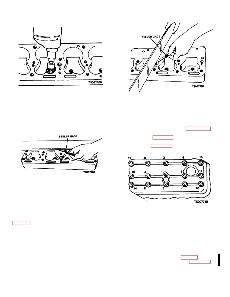
Figure 9-2. Cleaning Carbon From Combustion
Figure 9-4. Checking Cylinder Head Flatness Crosswise.
Chamber.
9-8.
Repair
b.
Clean the cylinder head thoroughly with a
Repair consists of replacement of a defective or,
solvent or degreasing solution and blow it off with air
otherwise unserviceable cylinder head.
pressure.
c.
Make sure that gasket contact surfaces on the
9-9.
Installation
head and block are clean, smooth and flat. See figure 9-
Reverse the procedures outlined in paragraph 9-6 for
3.
cylinder head installation.
a.
Refer to table 9-2 for fasteners torque
specifications.
b.
Refer to figure 9-6 for cylinder head bolt
tightening sequence.
Figure 9-3. Checking Cylinder Head Flatness
Lengthwise.
d.
Check out-of-flatness with straightedge and
feeler gage; maximum permissible is .00075 inches per
inch of width or length. Thus, for a cylinder head 16"
long, maximum permissible lengthwise out-of-flatness is
.012". Out-of-flatness should vary gradually and
Figure 9-5. Cylinder Head Bolt Tightening Sequence.
uniformly from end to end and side to side. Localized
depressions or high spots should not exceed .003 See
Section VI. INTAKE AND EXHAUST VALVES
exhaust valves seat in shrink-fit valve seat inserts in the
9-10.
General
block.
The intake and exhaust valves of this L-head engine
9-11.
Removal
are mounted in the cylinder block. They are opened by
operation of the camshaft through adjustable valve
a.
Remove the cylinder head (para 9-6).
tappets. They are closed by the valve springs. The valve
b.
stems ride in valve guides which are pressed into the
Remove the valve tappet cover (para 9-13.1).
block. The intake valves seat directly in the block. The
Change 1 9-5
|
|
Privacy Statement - Press Release - Copyright Information. - Contact Us |