 |
|||
|
|
|||
|
|
|||
| ||||||||||
|
|
 TM 10-3930-631-34
(a) Use a milli-voltmeter and touch voltmeter
(31.7 mm) inside diameter by 4.0 inches (101.6 mm)
probe to adjacent bars as shown.
long over commutator end against bearing shoulder on
(b) The meter will not show a reading unless the
shaft.
coil is open. If coils are open replace armature.
(c) Place armature in a press and apply vertical
(6) Inspect the commutator. If commutator is
pressure on short pipe at commutator end and press
burned, rough or out of round it must be resurfaced and
shaft from armature. Pressure to remove or install shaft
undercut.
may exceed 20 tons (18120 kg).
(a) Place armature in a lathe and turn
(d) To install new shaft, place a piece of pipe
commutator down until true.
Do not damage
1.5 inches (38.1 mm) inside diameter, 2.25 inches (57.1
commutator riser bars at rear of commutator when
mm) outside diameter against commutator end. Insert
resurfacing.
shaft as far as it will go. Place a piece of pipe 1.625
(b) Undercut mica between bars to a depth not
inches (41.2 mm) inside diameter by 3.0 inches (76.2
to exceed 0.030 inch (0.752 mm). Undercut must be full
mm) long against bearing shoulder on shaft and apply
width of mica and flat at the bottom. Undercut mica as
vertical pressure to press shaft into armature. Shaft
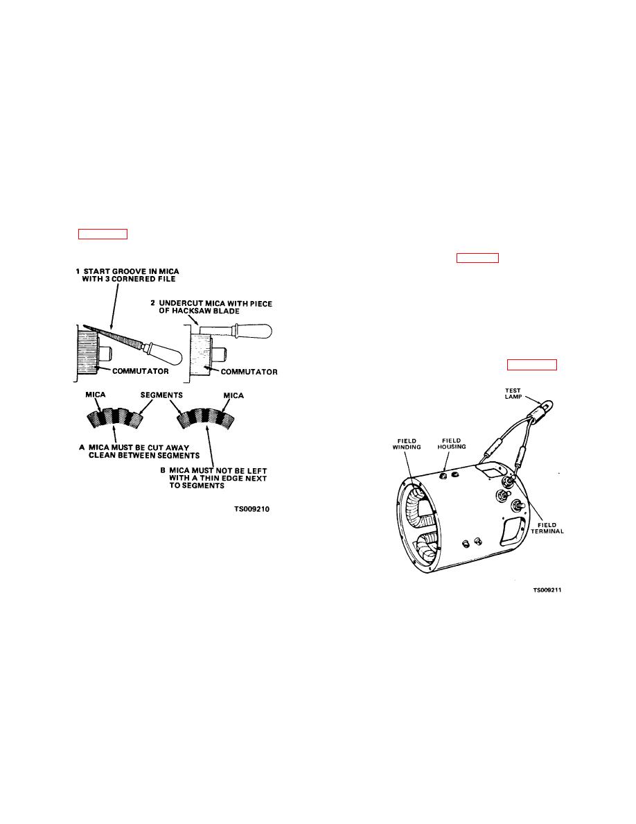
shown in figure 8-7.
must bottom against core support.
e. Assembly.
(1) Heat fan (8, fig. 8-3) in an oven to 200
degrees F (93 degrees C). Position key (9) on shaft and
press fan into place. Install retaining ring (7) to secure
fan.
(2) Position pole shoes (30) and shims (31) in
housing. Install field windings (32) and connect stud
assemblies (10 and 11) to frame and windings. Install
pole shoes screws (29).
(3) Connect a test lamp between the field
terminal and the housing as shown in figure 8-8.
Figure 8-7. Undercutting mica.
(c) After undercutting clean out slots to remove
any dirt and copper dust.
(d) Lightly rub the commutator with sandpaper
to remove any burs left from undercutting.
Figure 8-8. Checking field winding for grounds.
(7) Inspect armature shaft for wear and
damage. If shaft requires replacement proceed as
follows:
(a) Place drive end of shaft in a heavy duty pipe
2.25 inches (57.1 mm) inside diameter by 18 inches
(457.2 mm) long. Pipe must be in complete contact with
core above shaft but within the radius of the core rivets.
(b) Place another piece of pipe 1.5 inches
8-5
|
|
Privacy Statement - Press Release - Copyright Information. - Contact Us |