 |
|||
|
|
|||
|
Page Title:
Section II. HYDRAULIC PUMP MOTOR |
|
||
| ||||||||||
|
|
 TM 10-3930-631-34
(4) If lamp lights, field winding is grounded.
(6) Secure bearing housing with screws (3).
Remove winding and check to locate short. If short
(7) Place motor housing in a vertical position.
cannot be located and repaired replace field windings.
Use a hoist and carefully lower armature assembly with
(5) Pack bearing (6) half full of grease (GA).
housing. Do not damage commutator, core or field
Install seal (5) and bearing (6) in bearing housing (4).
windings.
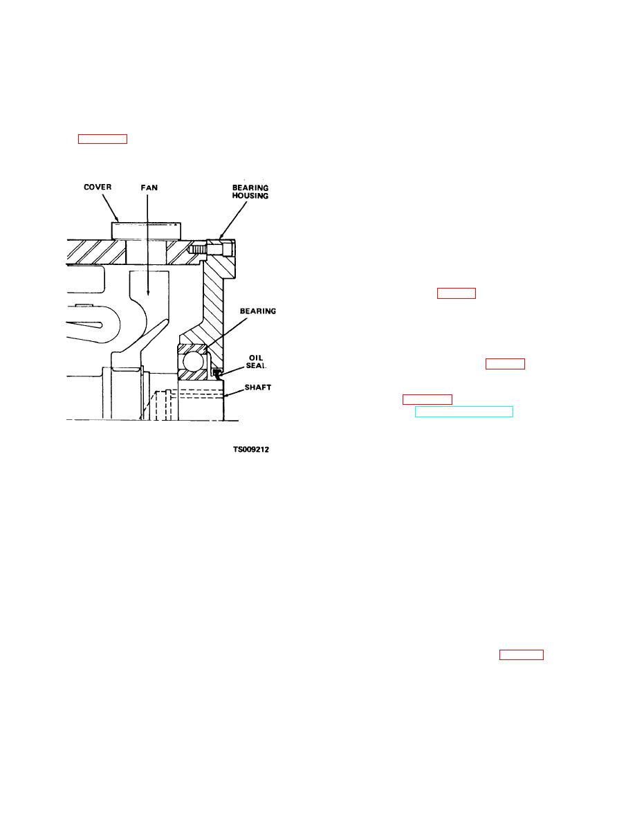
Install bearing housing on housing (33) with seal as
(8) Install brush holders (22) and springs (23)
shown in figure 8-9.
on rocker arm (26). Connect leads (13,14 and 15) to
windings and rocker arm.
(9) fill bearing (27) half full of grease (GAA) and
install bearing in housing (28). Install assembled rocker
arm in housing and secure with screws (24) and lock
washers (25).
(10)Install bearing housing over commutator and
secure with screws (12).
(11)Refer to paragraph a. above and install
brushes.
(12)Install covers (1) and (2) on drive motor.
f. Installation.
(1) Place drive motor in position under truck.
Install new gasket (9, fig. 3-8) on carrier. Use a suitable
jack and lift drive motor into position in line with
differential carrier. Guide motor shaft to engage splines
of pinion gear in carrier and aline motor mounting holes
with holes in differential carrier.
(2) Secure motor to carrier with screws (5) and
lock washers (6). Install disk (5, fig. 4-1) on motor shaft
and secure with nut.
(3) Install parking brake bracket and calipers on
drive motor (para 4-1) and connect parking brake
linkage. Refer to TM10-3930-631-12 and adjust parking
brake linkage.
(4) Connect electric cables to drive motor.
Connect leads to thermal relay on motor.
(5) Install drip pan and floor and toe pates. Fill
axle and differential with proper grade of oil (LO10-3930-
631-12).
Figure 8-9. Installing bearing housing.
Section II. HYDRAULIC PUMP MOTOR
closes micro-switches allowing the current to flow to the
8-3. Description
pump motor.
a. The hydraulic pump and motor are mounted
8-4. Repair of Hydraulic Pump Motor
horizontal to the frame to the rear of the drive motor. As
a. Brush Replacement.
the motor drives the pump, hydraulic oil is delivered
(1) Disconnect battery receptacle and discharge
under pressure to the control valve. From the control
capacitors.
valve the oil is sent to actuate lifting, tilting and shifting
(2) Raise front end of truck and securely block
cylinders.
b. The pump motor is a ventilated, sealed ball
truck. Remove drip pan to gain access to hydraulic
pump and motor.
bearing type motor. The motor is supported at each end
(3) Remove rear cover (13, fig. 8-10) to gain
on brackets attached to the truck frame. Current is
access to brushes.
supplied to the motor when the key switch is on and
either lift, tilt or side shift control valve levers are
actuated. Movement of the levers
8-6
|
|
Privacy Statement - Press Release - Copyright Information. - Contact Us |
