 |
|||
|
|
|||
|
Page Title:
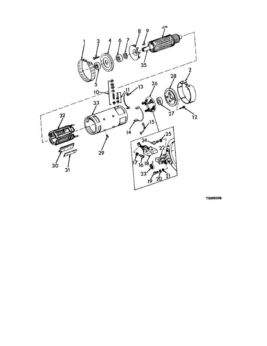
Figure 8-3. Drive motor, exploded view. |
|
||
| ||||||||||
|
|
 TM 10-3930-631-34
1. Front cover
13.
Lead
25.
Lock washer
2. Rear cover
14.
Lead
26.
Rocker arm
3. Screw
15.
Lead
27.
Bearing
4. Bearing housing
16.
Screw
28.
Housing
5. Seal
17.
Lock washer
29.
Screw
6. Bearing
18.
Brush assembly
30.
Pole shoe
7. Retaining ring
19.
Screw
31.
Shim
8. Fan
20.
Lock washer
32.
Field winding
9. Key
21.
Washer
33.
Housing
10. Stud assembly
22.
Brush holder
34.
Armature
11. Stud assembly
23.
Brush spring
35.
Shaft
12. Screw
24.
Screw
Figure 8-3. Drive motor, exploded view.
(2) Place motor on end with drive end up.
Note
(3) Remove screws (3) securing housing (4) to
Lift armature straight up to prevent damage to
motor. Attach a chain and hoist to housing and lift
commutator, pole shoes and windings.
armature, bearings, retainer and housing from field
(4) Wrap commutator with heavy paper to
housing (33).
8-3
|
|
Privacy Statement - Press Release - Copyright Information. - Contact Us |