 |
|||
|
|
|||
|
Page Title:
Camshaft, Reassembly and Installation |
|
||
| ||||||||||
|
|
 TM 10-3930-630-34
11-26. Camshaft, Reassembly and Installation
block and bearings.
b. Install thrust plate (6) and secure with screws (4)
and lock washers (5).
c. Install camshaft gear (2) and key (3) on shaft
(7). Secure gear with nut (1). Tighten nut to a torque of
175 to 180 foot pounds (24.1 to 24.8 cm/kg).
d. Make sure the marked teeth on the camshaft
gear straddle the marked tooth on the crankshaft gear
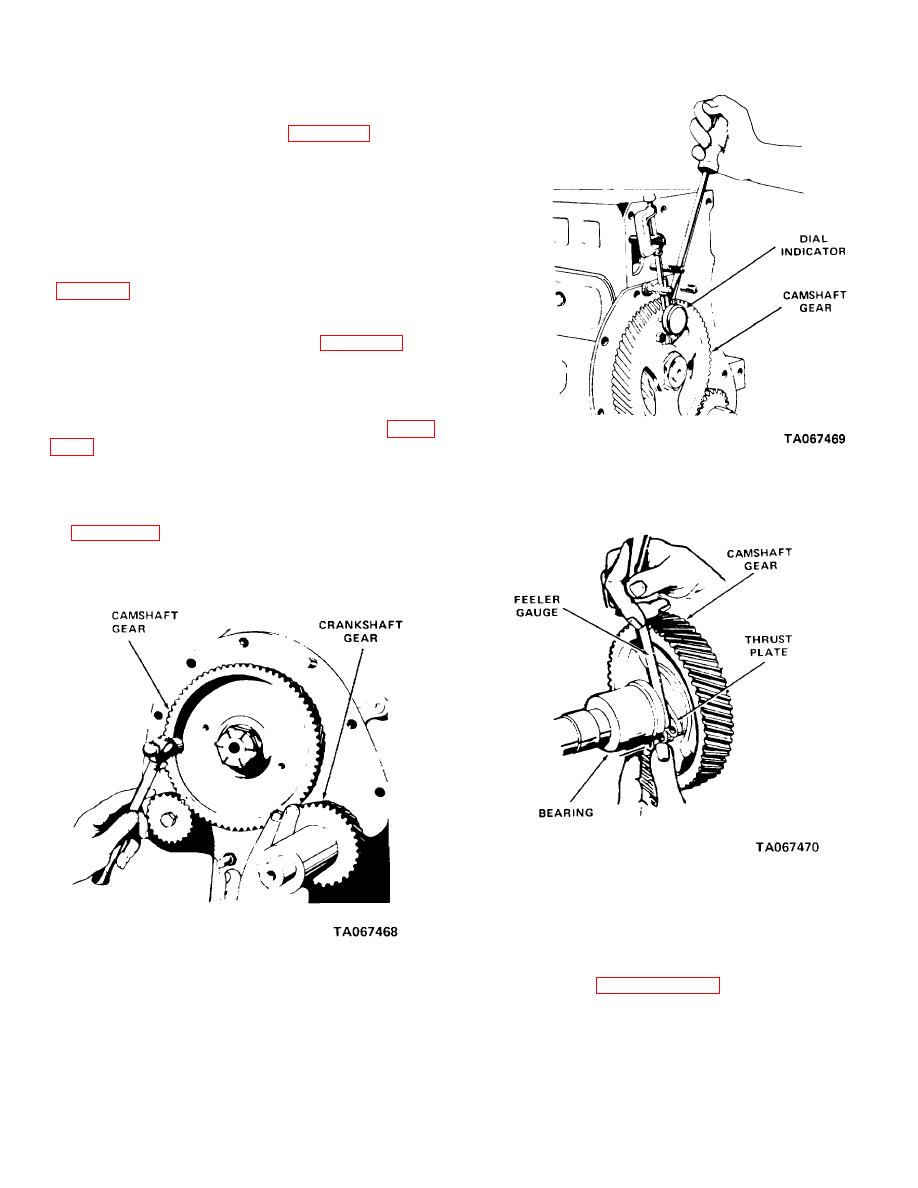
e. To make sure there is enough clearance, hold
finger at junction of the two gears and tap the rim of the
camshaft gear with a light hammer (fig. 11-28) and
check for vibration. Check fit of teeth with an 0.0015
inch (0.038 mm) feeler gage between teeth.
(1) If vibration is felt and feeler gage will not fit
between gears, the gear fit is within expectations.
(2) Install a dial indicator as shown on figure
0.009 to 0.005 inch (0.228 to 0.127 mm).
Figure 11-29. Checking camshaft end play.
f. Check camshaft end play. End play must be
0.009 to 0.005 inch (0.228 to 0.127 mm).
(1) Check camshaft thrust clearance as shown
(2) If camshaft end play does not conform to
tolerances stated above, it may be corrected by
Figure 11-30. Checking camshaft thrust clearance.
installing a new thrust plate. If this does not correct the
condition, it may be necessary to machine a small
amount off from the shoulder of the thrust plate that
engages the rear face of the gear.
Figure 11-28. Checking camshaft gear fit.
and gear cover.
11-21
|
|
Privacy Statement - Press Release - Copyright Information. - Contact Us |