 |
|||
|
|
|||
|
|
|||
| ||||||||||
|
|
 TM 10-3930-630-34
(3) Linings severely burned or charred.
9-3. Service Brake, Cleaning, Inspection and Repair
(4) Linings deeply scored.
NOTE
(5) Brake mounting worn, twisted or out of round.
When handling brake shoes, be
(6) Cracked shoes.
careful not to get grease or dirt on
brake linings as serious damage may
linings. If replacement is necessary, the complete brake
result.
shoe must be replaced.
return spring (1, fig. 9-1) must have a free length of 7.5
9-4. Service Brake, Reassembly and Installation
inches (190.5 mm) inside hoops, initial tension must be
a. Service brakes are reassembled during the
30 pounds (13.5 kg) and initial stretch of 0.5 inch (12.7
installation procedure.
Install and reassemble the
mm). Lower return spring (2) must have a free length of
service brake in reverse numerical sequence as
3.0625 (77.7 mm) inside hooks, initial tension of 30
illustrated in figure 9-1.
pounds (13.5 kg) and initial stretch of 0.25 inch (6.35
mm). Replace unserviceable springs.
wheels.
b. Brake shoe replacement is necessary if any of the
following problems are observed.
(1) Lining worn to shoe mounting.
(2) Grease or hydraulic fluid soaked linings.
Section II. WHEEL CYLINDER
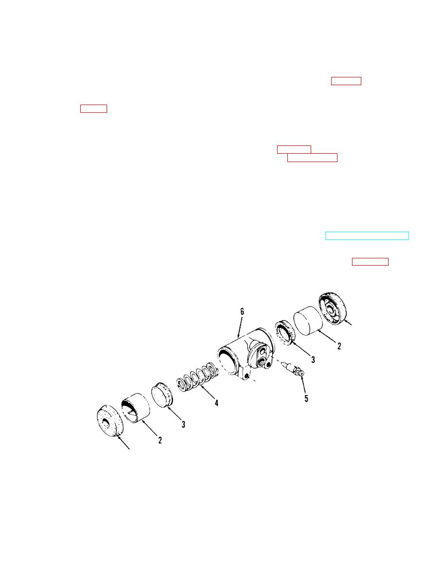
9-6.Wheel Cylinder, Removal and Disassembly
9-5. Description
a. Removal. Refer to TM 10-3930-630-12 and
a. The hydraulic wheel cylinder houses two opposed
remove the wheel cylinder.
pistons which actuate the opposed brake shoes. The
b. Disassembly. Disassemble the wheel cylinder in
pistons, rubber cups and springs are held in place, in the
cylinder, by the brake shoe mechanical pressure.
numerical sequence as illustrated in figure 9-2.
b. The open ends of the cylinders are protected with
rubber boots.
TA067428
1 Cylinder boot
4 Spring
2 Cylinder piston
5 Bleed screw
3 Piston cup
6 Cylinder body
Figure 9-2. Wheel cylinder, disassembly and reassembly.
9-2
|
|
Privacy Statement - Press Release - Copyright Information. - Contact Us |
