 |
|||
|
|
|||
|
Page Title:
Parking Brake Lever and Linkage |
|
||
| ||||||||||
|
|
 TM 10-3930-630-12
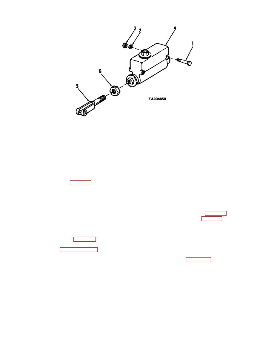
1 Screw
2 Lockwasher
3 Nut
4 Master cylinder
5 Clevis
6 Nut
Figure 4-75. Service brake master cylinder, removal and installation
brake with a cable.
(4) Remove (6) and clevis (5) from master
b. Adjustment. To compensate for brake lining
cylinder (4).
d. Installation.
wear the parking brake lever can be adjusted. If the
adjusting knob on the parking brake lever will no longer
(1) Install nut (6, Fig. 4-75) and clevis (5) on
provide correct brake adjustment and sufficient brake
master cylinder.
lining is still available, further adjustment can be made
(2) Install master cylinder on truck and secure
with the brake cable.
with screws (1), lockwashers (2) and nuts (3). Connect
(1) Place brake lever in the fully released
ground wire to rear master cylinder mounting screw.
position.
NOTE
(2) Remove setscrew (Fig. 4-76) in brake lever
adjusting knob. Rotate knob (Fig. 4-76) one or two turns
Internal-external tooth lockwashers (2)
clockwise. Check adjustment by engaging brake.
must be installed with mounting screws for
(3) Repeat adjustment ((2) above) as
radio suppression.
necessary to assure correct lining contact with drum.
After adjustment is correct, install setscrew to secure
(3) Connect clevis (Fig. 4-69) to brake pedal
adjusting knob.
adjust pedal travel (par 4-87) as necessary.
(4) If above steps do not provide proper
(4) Refer to paragraph 4-89 to fill master
braking action, adjust cable.
cylinder and bleed brake system.
(5) Refer to figure 4-77 and remove cotter pin,
4-91. Parking Brake Lever and Linkage
washer and clevis pin securing clevis to cam lever.
a. General The parking brake lever mounted next
to the instrument panel is connected to the parking
4-83
|
|
Privacy Statement - Press Release - Copyright Information. - Contact Us |