 |
|||
|
|
|||
|
|
|||
| ||||||||||
|
|
 TM 10-3930-630-12
TA0M34780
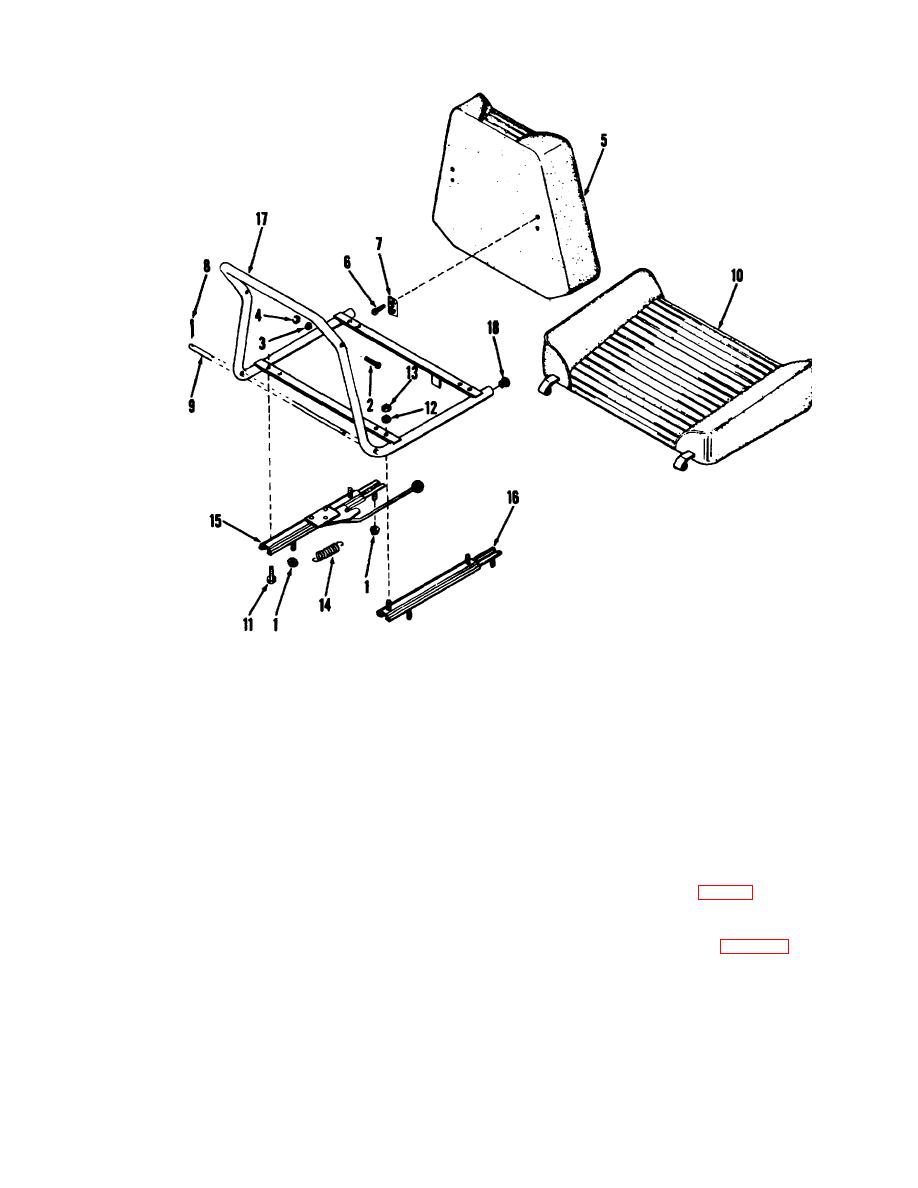
1 Nut
10 Seat cushion
2 Screw
11 Screw
3 Washer
12 Lockwasher
4 Nut
13 Nut
5 Backrest
14 Spring
6 Screw
15 Slide adjuster
7 Hinge
16 Slide
8 Cotter pin
17 Frame
9 Rod
18 Plug
Figure 4-5. Seat assembly, exploded view.
Section XI. INSTRUMENT PANEL
4-31. General
a. The instrument panel is mounted across the
instruments for correct reading (fig. 2-1). Test fuses with
front of the truck forward of the steering wheel All the
an ohmmeter for continuity.
instruments relative to truck operation are mounted on
b.
Removal
the pane
(1) Remove clamps (1, fig. 4-8). Remove
b. Also mounted on the panel are the ignition
screw (2), lockwasher (3) and nut (4) and remove clamp
switch and choke control The ignition switch serves to
(5).
start the truck, as a starter switch and the main switch in
(2) Disconnect frame wiring harness (7) from
the electrical system.
instrument panel harness.
(3) Remove clamp (6). Remove screws (9),
4-32. Instrument Panel
lockwashers (10) and nuts (11) and remove adapter (12)
a. Test. Operate truck engine and truck.
and choke control (8) from panel Remove harness (7).
Check
4-15
|
|
Privacy Statement - Press Release - Copyright Information. - Contact Us |