 |
|||
|
|
|||
|
|
|||
| ||||||||||
|
|
 TM 10-3930-628-12
4-40.
General
steering and pivot arms. Movement of the pivot arm
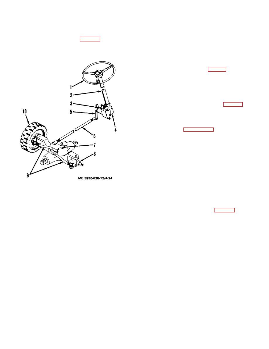
a. The steering system (fig. 4-24) is manually
pulls the tie rods in unison moving the wheels in direction
operated. Main components are the steering wheel,
of the turn desired.
steering column, steering gear, steering arm, and drag
4-41.
Steering Wheel
link.
a. Removal.
(1) Refer to paragraph.4-24 and remove the
horn button.
(2) Remove screws (10, fig. 4-7) and remove
base plate (2).
(3) Remove nut (11).
(4) Using a suitable puller, pull steering wheel
(1) from steering gear shaft. Remove spring
(12).
b. Installation.
(1) Install steering wheel (1, fig. 4-7) and
spring (12) on steering shaft. Secure wheel with nut
(11).
(2) Install base plate (2) and secure with
screws (10).
(3) Refer to paragraph 4-21 and install horn
button.
4-42. Steering System Adjustments
a. General. Adjustments required consist of
wheel toe-in, pivot arm stops and steering arm stops.
b. Toe-In.
(1) Place a jack under rear of truck and raise
truck far enough to provide working clearance; Place
blocks under truck to hold in raised position. Block front
wheels to prevent movement.
(2) Remove toe and floor plates to gain access
to steering arm and steering gear.
1.
Steering wheel
(3) Rear wheels should be in line with and
2.
Steering column
parallel to frame with zero toe-in. Turn steering wheel
3.
Filler plug
from lock to lock, counting number of turns. Center
4.
Steering gear assembly
steering wheel and check wheel toe-in.
5.
Steering arm
(4) Remove cotter pin (13, fig. 4-25) and nut
6.
Drag link
(12). Remove boot (11) and tap ball socket (10) from
7.
Pivot arm
wheel spindle.
8.
Wheel spindle
(5) Loosen nut (8) and adjust length of tie rods
9.
Tie rods
to bring wheels in line with frame by turning ball socket
10.
Rear wheel
(10) in or out of tie rod/tube (7). Torque nut (8) to 50-70
Figure 4-24. Steering system.
foot-pounds to cure adjustment.
b. The drag link (6) connects to the pivot arm
(6) Install ball socket (10 in spindle and secure
(7) on the rear, or steering axle. Two tie rods (9) extend
with boot (11), nut (12 and cotter pin (13).
from the pivot arm to the wheel spindles (8). Rotation of
the steering wheel (1) moves the
4-25
|
|
Privacy Statement - Press Release - Copyright Information. - Contact Us |