 |
|||
|
|
|||
|
|
|||
| ||||||||||
|
|
 TM 10-3930-628-12
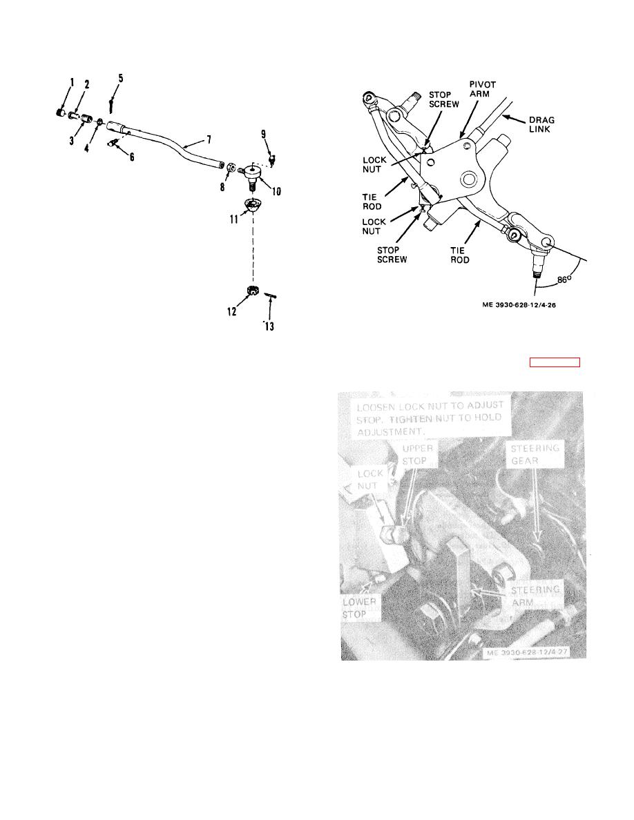
Figure 4-26. Pivot arm stop adjustment
1.
Adjusting plug
8. Nut
(3) With the pivot stop screws adjusted ( (2)
above) adjust the steering arm stops (fig. 4-27) to
2.
Ball ,seat
9. Lubrication fitting
contact steering arm at same time spindle contacts stop
screws.
3.
Spring
10. Ball socket
4.
Spacing washer
11. Boot
5.
Cotter pin
12. Nut
6.
Lubrication fitting
13. Cotter pin
7.
The rod tube
Figure 4-25. Tie rod, exploded view
c. Pivot and Steering Arm Stops.
(1) Turn wheels full right or full left.
(2) Adjust the pivot arm stop screws (fig. 4-
261 to allow 1/2 inch clearance between tire and steering
axle with the wheels turned full right and full left. Stop
screws should limit spindle travel to 860 as shown.
Torque stop screw locknuts to 2-3 toot-pounds.
Figure 4-27. Steering arm stop adjustment.
4-26
|
|
Privacy Statement - Press Release - Copyright Information. - Contact Us |