 |
|||
|
|
|||
|
|
|||
| ||||||||||
|
|
 c. Assembly.
(1) Thoroughly wet all internal parts with
lubricating oil OE10 before installation. Take particular
care to keep parts clean during assembly.
(2) Install piston and rod (13) in cylinder (14), to
bottom. Fit packing (12) into recess in cylinder, lay
packing (11) on top of it, and install stuffing box (10) in
cylinder snugly with spanner wrench.
(3) Slide packing set (9) down piston rod,
carefully entering it into recess of stuffing box.
(4) Lubricate and install wiper ring (8) in recess of
packing retainer (5) and install packing retainer (loosely
at first) with screws (6) and washers (7).
(5) Install rod end (1) on piston rod, and replace
screw (3) washer (4) and nut (2), but do not tighten, as
rod end final position must be adjusted when tilt cylinder
is installed.
(6) Operate tilt control to test operation and check
for leaks.
(7) Correct leaks around piston shaft by evenly
tightening both screws (6) only enough to stop major
fluid leakage past packing (9). Slight weeping of fluid
onto rod is desirable for lubrication and corrosion
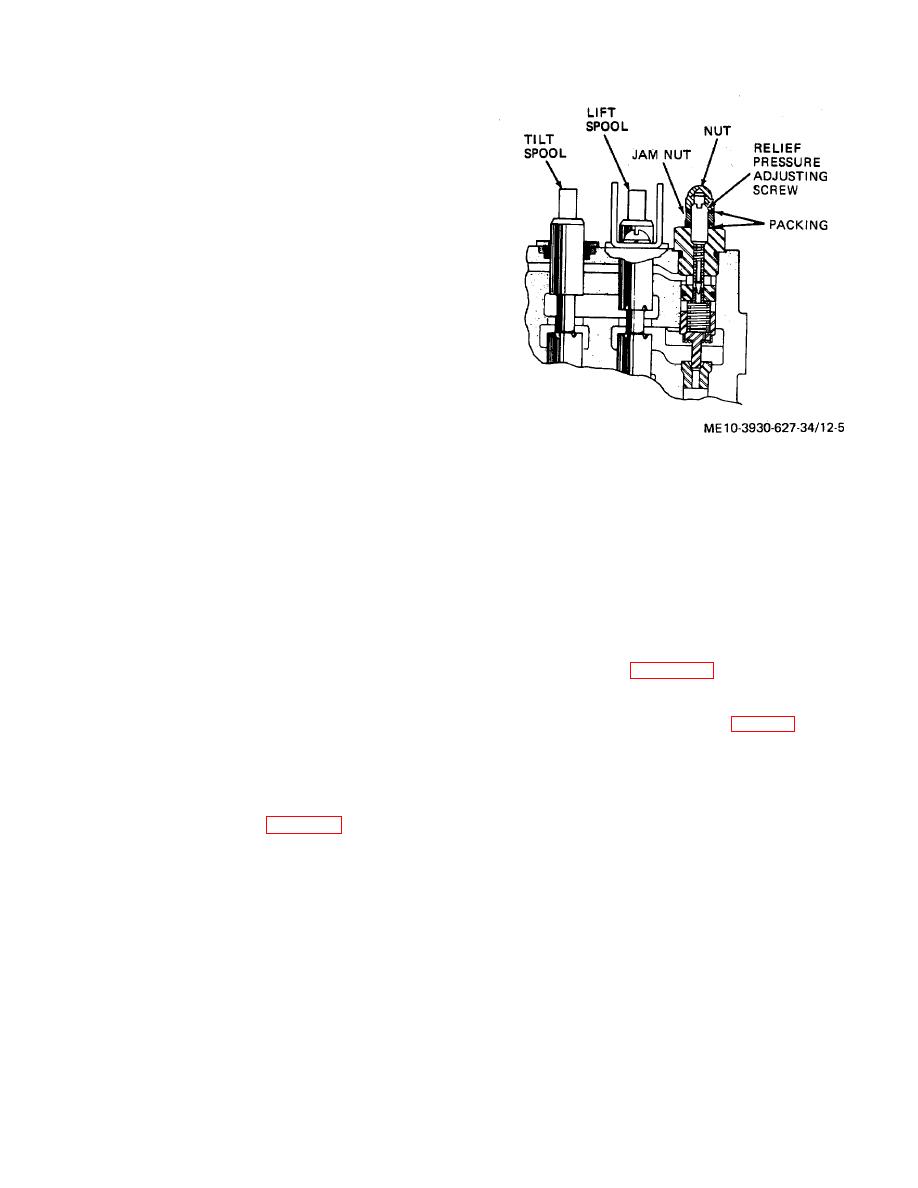
Figure 12-5. Hydraulic system relief valve adjustment.
protection. Do not tighten screws more than just enough
to stop leakage. Shafts should not run dry at any time.
c. Disassembly.
12-6. Control Valve Repair
Caution: This valve contains numer -
ous similar appearing, but not
a. Removal and Installation. Refer to TM 10-3930-
interchangeable, parts. Before dis-
627-12.
assembly, arrange separate contain-
b. Adjustment. Adjustment procedures given here
ers for parts related to each spool to
presume the valve is installed on a serviceable truck. If
avoid problems at assembly. Equiva -
dismounted valve is to be adjusted for return to stock,
lent parts with different index
use same procedure, getting hydraulic pressure from a
hydraulic test set, and plug ports before storing valve.
numbers on figure 12-6 are not inter-
Proceed as follows:
changeable.
(1) Install shaft through HOIST and TILT levers,
spacing levers with spacers within bracket.
(1) Unscrew plug and seal (1, fig. 12-6). Remove
(2) When levers are positioned satisfactorily,
nut (2), nut (4) and seals (3). Back out setscrew (5), and
install three cotter pins to secure shaft.
remove spring (6) and plunger (7). Remove safety relief
(3) Disconnect upper TILT hose, and insert a
valve cap (12) and packing (9).
hydraulic pressure gage scaled to read to 2000 pounds
(2) Remove packing (10) and retainer (11), seat
per square inch in port.
(8), spring (13), screen (14), plunger (15) and seat (16).
(4) Remove cap nut (fig. 12-5) and insert
(3) Remove check valve cap (17), packing (18),
screwdriver in slot of adjusting setscrew. With engine
spring (19) and poppet (20).
running move TILT control lever to UP position, and turn
(4) Remove screws (22) and brackets (21) from
adjusting setscrew as necessary to cause pressure gage
both TILT and HOIST valves. Remove wipers (23),
to indicate 1700 to 1900 pounds per square inch. Lock
packing retainers (24) and packings (25).
adjustment with nut and recheck setting after tightening
(5) Take off both spool caps (26), and remove
nut.
retaining rings (27 and 34), four spring retainers (28 and
35), springs (29 and 36), and washers (30 and 37).
(6) Remove packing retainers (31 and 38) and
packings (32 and 39).
12-8
|
|
Privacy Statement - Press Release - Copyright Information. - Contact Us |