 |
|||
|
|
|||
|
|
|||
| ||||||||||
|
|
 TM 10-3930-627-12
(2) If output is not as specified, replace
instead of the 13.6 to 14.3 volts given for the middle or
"0" position.
Note. Additional tests and repairs are beyond
(4) If the actual regulating voltage as
checked is not within the voltage range specified for the
scope of equipment available at organizational
measured ambient temperature, replace the regulator.
maintenance. Refer defective alternators to direct or
(5) If the actual regulating voltage as
general support maintenance.
checked is within the voltage range specified for the
4-32. Alternator Voltage Regulator
measured ambient temperature, the charging system
a. Test.
operation is satisfactory. However, the voltage setting of
(1) Run engine at about 1500 rpm for 15
the regulator may need to be changed to meet the
minutes with spotlight on, and a thermometer placed
battery charging requirements for the type of driving
about 1/4 inch from the regulator cover.
being done. To properly adjust the voltage setting, refer
(2)
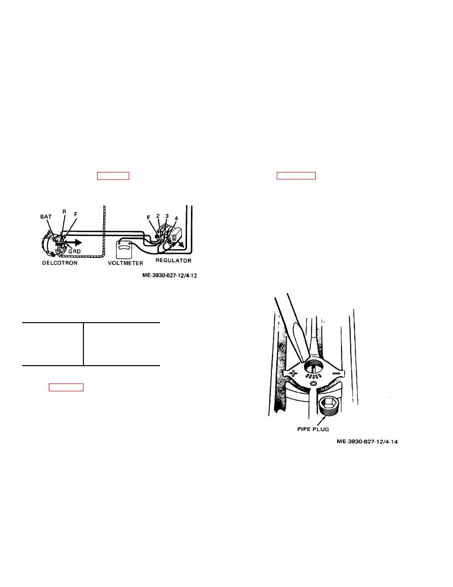
With engine running, connect a
to b below.
voltmeter to ground at the regulator base, and to either
b. Voltage Adjustment. To adjust the voltage
number 3 or number 4 terminal of the regulator (fig. 4-
regulator setting, remove the access plug from the
13). Compare temperatures and voltage reading with
regulator (fig. 4-14).
Then to correct for an
values given below in table 4-3 to learn if regulator is in
undercharged battery insert screwdriver into slot and turn
specified operating range.
clockwise one notch (0.3 volt) to increase the setting. To
correct for an overcharged battery, turn counterclockwise
one notch (0.3 volt) to decrease setting. Then check for
an improved battery condition over a service period of
reasonable length. If necessary, repeat the above
procedure for a higher or lower setting.
Note. Additional tests and adjustments of the
regulator are beyond the scope of equipment normally
available at organizational maintenance. If troubles are
not corrected, refer to direct or general support
maintenance.
Figure 4-13. Voltage regulator rest setup.
Table 4-3. Regulator Voltage Specifications
A+65 deg. F.
14.1 to 14.8 volts
A+85 deg. F.
13.9 to 14.7 volts
A+105 deg. F.
13.7 to 14.5 volts
A+125 deg. F.
13.6 to 14.3 volts
A+ 145 deg. F.
13.4 to 14.2 volts
(3) If actual voltage is not within the
specified range, remove access plug from regulator
cover (fig. 4-14) and note the position of the plastic
screw slot beneath the plug. The slot will be lined up
with one of the divisions or lines cast on the regulator
cover. For each division the slot has been moved
clockwise from the middle position ("0" position) or
toward the "+ " cast on the cover, add 0.3 volt to the
above specified range for the proper specified voltage
limits. For each division the slot has been moved
counterclockwise from the middle ("0" position) or toward
Figure 4-14. Regulator adjustment screw.
the "-" on the cover, subtract 0.3 volt from the above
specified range for the proper specified voltage limits.
c. Replacement. Unplug wiring harness from
As an example, assume that the slot is lined up with the
regulator, and remove mounting screws from base
second line from the "0" nearest the "+" mark. This
position would require adding of 0.6 volt to the
specification voltage shown in the specification table.
The limits at 1250 would become 14.2 to 14.9 volts
4-19
|
|
Privacy Statement - Press Release - Copyright Information. - Contact Us |