 |
|||
|
|
|||
|
|
|||
| ||||||||||
|
|
 TM 10-3930-627-12
(3) If the thermostat opens before the
(7) Loosen outlet (lower) radiator hose
water temperature reaches 1600F. or does not open
clamp and separate hose from water pump (7) and from
until after the water temperature reaches 1800F., it
radiator. Disconnect remaining hoses from radiator.
should be replaced.
(8) Remove mounting capscrews and lock
c. Inspection. Inspect adapter for deterioration.
washers, remove adjusting strap cap screws, and
remove water pump (7) and gasket from engine block.
Inspect elbow .(housing) for cracks and thread for
(Bottom cap screw has copper washer.)
damage.
d. Installation. Reverse procedure in a above,
(9) Remove screws at sides of radiator and
remove radiator.
using a new gasket between the elbow and the cylinder
b. Inspection.
head. Make sure split in adapter aligns with bypass hole
(1) Inspect the pump for secure mounting.
in elbow.
(2) Inspect the water pump bearing for
4-30. Water Pump, Fan, Belt, and Radiator
noise.
a. Removal.
(3) Inspect the fan for secure mounting,
(1) Loosen alternator adjusting strap bolt at
bent or cracked blades.
water pump.
(4) Inspect the fan belt for wear, frays, and
(2)
Loosen alternator mounting bolts
proper adjustment of /2 inch finger-pressure deflection at
securing to mounting support and remove belt from
midpoint between the crankshaft pulley and the fan
alternator and crankshaft pulleys.
pulley.
(3) Work fan belt (6, fig. 4-11} over fan (1)
c. Installation. Reverse steps of a above, in-
and rotate fan until belt can be removed from the fan.
stalling a new water pump gasket. Refill cooling system.
(4) Remove screws (8) and lockwashers
d. Adjustment of Belt.
that secure fan to hub. Remove fan (1).
(1) Loosen the alternator adjusting strap
(5) Drain radiator.
bolt and the alternator mounting bolts.
(6) Disconnect recirculating tube (4) at
(2) Pivot alternator for desired belt tension
water pump and at thermostat elbow and remove from
(b (4) above) and tighten adjusting strap bolt and
engine.
alternator mounting bolts.
Section X. ELECTRICAL SYSTEM
specified output of 14 volts. Check amperage at 2000
4-31. Alternator
alternator rpm or 1000 engine rpm (cold); it should be 21
a. Removal.
amperes. Check amperage at 5000 alternator rpm or
(1) Disconnect wiring harness and ground
2500 engine rpm (cold); it should be 30 amperes.
lead at front of alternator.
Operate alternator until it is at operating temperature.
(2) Remove attaching screw at adjusting
Check output amperage; it should be 32 amperes
strap (fig. 4-11 ) and screws at mounting bracket, and lift
maximum.
off alternator.
b. Installation.
(1) Position alternator on mounting bracket
and install screws attaching alternator to mounting
bracket and adjusting strap.
(2) Install drive belt on alternator pulley,
and adjust drive belt tension so that drive belt can be
deflected one-half inch by finger pressure at midpoint
between drive and driven pulleys. To adjust tension,
loosen cap screw that holds adjusting strap to alternator
and loosen screws that hold alternator to mounting
bracket. To tighten, use bar to pry alternator away from
engine to achieve correct tension; then tighten adjusting
strap cap screw. Tighten mounting screws.
(3) Reconnect wiring harness and ground
lead to alternator.
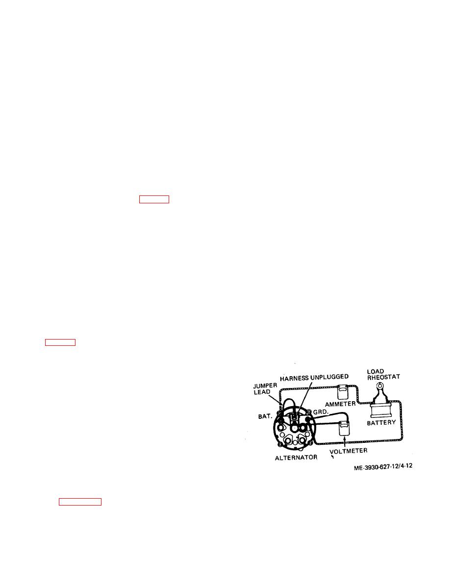
Figure 4-12. Alternator test setup.
c. Test.
(1)
Connect assembled alternator as
shown in figure 4-12. Make sure negative terminal is
connected to ground. Adjust load rheostat to obtain
4-18
|
|
Privacy Statement - Press Release - Copyright Information. - Contact Us |