 |
|||
|
|
|||
|
Page Title:
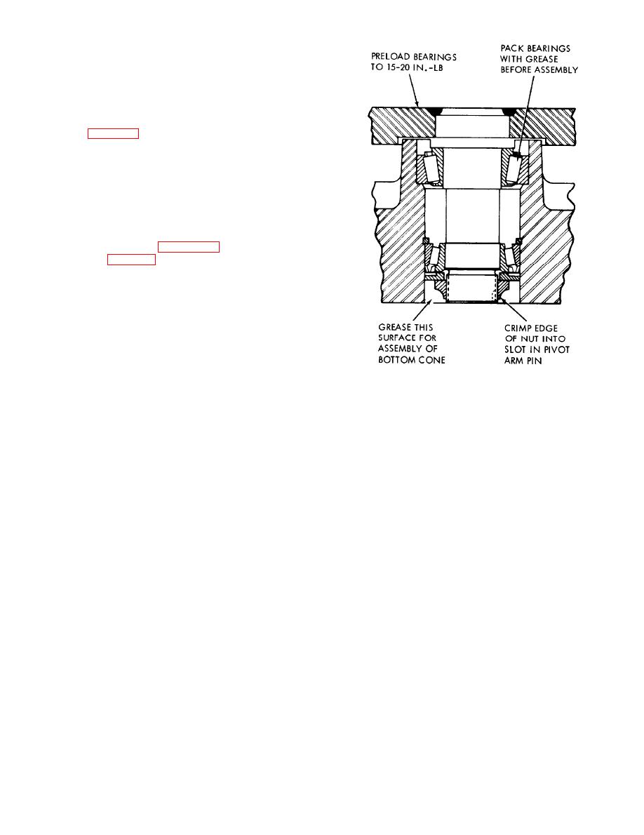
Figure 4-18. Pivot arm bearings. |
|
||
| ||||||||||
|
|
 tightness of ball studs and pins in pivot arms.
Inspect all the bearings, tie rods parts, ball studs,
and ail other parts for damage or excessive wear.
(3) Replace any parts which show excessive
wear or damage.
d. Reassembly. Reassemble the components in
reverse o r d e r o f d i s a s s e m b l y o b s e r v i n g t h e
following :
(1) Hand pack the king pin needle bearings
(39, fig. 4-17) with wheel bearing grease, and
grease the thrust washers (38). Position each
spindle (36 and 37) and thrust washer in the steer
axle (40). Position the king pin (33) with the slot
toward the top. Make sure the roll pin hole in the
spindle will lineup with the roll pin hole in the king
pin.
(2) Hand pack the pivot arm bearings (27 and
30) with wheel bearing grease, and press them into
the steer axle. See figure 4-18. Position the pivot
arm (25, fig. 4-171, pivot arm bearings and bearing
cups (27 and 30), lock ring (28), washer (24), and
retaining nut (23) in the steer axle. Pre-load the
pivot arm bearings to 15-20 in. lbs. Crimp the
edge of the retaining nut (23) into the slot in the
pivot arm pin.
ME 3930-624-34/4-18
Figure 4-18. Pivot arm bearings.
4-19
|
|
Privacy Statement - Press Release - Copyright Information. - Contact Us |