 |
|||
|
|
|||
|
|
|||
| ||||||||||
|
|
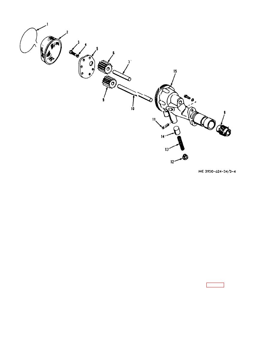
 11. Pin
6. Idler gear
1. Wire
2. Screen
7. Idler shaft
12. Retainer
13. Spring
8. Gear
3. Capscrew
4. Lockwasher
9. Drive gear
14. Piston
5. Cover
10. Drive shaft
15. Body
Figure 3-4. Oil pump, exploded view.
(2) Remove the idler gear (6) and the idler
(4) Install the gears and shafts in the pump
shaft (7).
body. Radial clearance between the gears and
(3) Place the pump in a press and remove the
pump body should be 0.001 to 0.002 inch. End
gear (8). Place a drift on the drive shaft and remove
clearance between the gears and pump cover should
the drive gear (9) and drive shaft (10).
be 0.002 to 0.004 inch and must not exceed 0.006
inch. Backlash between the pump gears should not
(4) Remove the pin (11). retainer (12), spring
exceed 0.020 inch. Replace parts as required.
(13) and piston (14).
Replace the pump if clearances are not maintained.
c. Cleaning and Inspection.
d. Reassembly. Assemble the oil pump in the
(1) Clean in a suitable solvent and dry with
reverse order of disassembly. Observe the
compressed air.
following :
(2) Inspect the gear teeth, inside of pump
housing and inner face of the cover for scratches,
(1) Press the gears (6 and 9, fig. 3-4) onto the
shafts (7 and 10) so that the gears are flush with the
cracks. nicks, burrs. scoring and other surface
damage. Smooth surfaces with a soft hone or crocus
ends of the shafts.
cloth or replace as required.
(2) Lubricate the shafts (7 and 10) before
(3) Inspect the pump shafts and shaft bores for
installing in the body.
scoring and wear.
3-6
|
|
Privacy Statement - Press Release - Copyright Information. - Contact Us |