 |
|||
|
|
|||
|
Page Title:
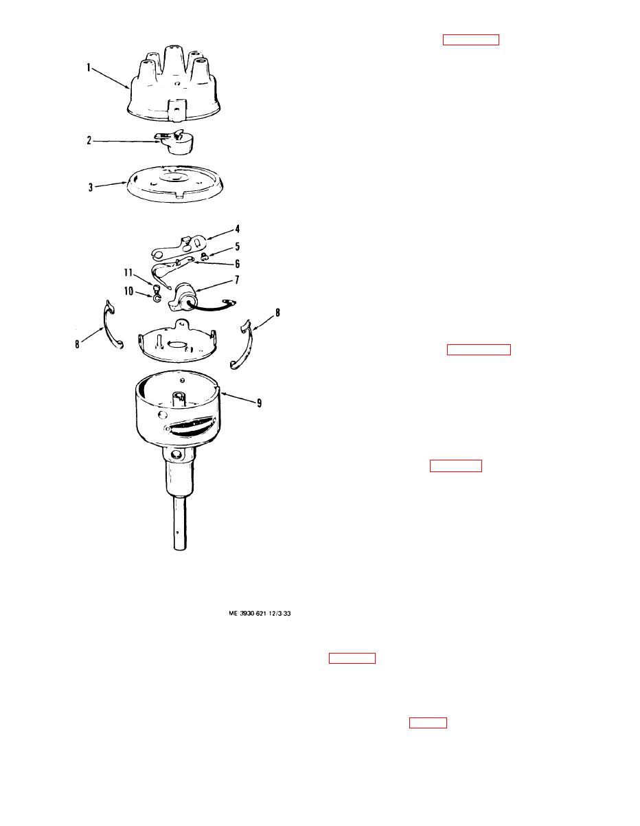
Figure 3-33. Ignition distribution, exploded view |
|
||
| ||||||||||
|
|
 ble the distributor far enough to replace rotor and
contacts as follows:
(1) Release cap retaining springs (8) and remove
cap (l), rotor (2), and dust cover (3), from housing
(9).
(2) Remove breaker lever (6) from pin. Remove
two screws (5) and remove contact assembly (4).
(3) Disconnect wire and remove screw (11) and
lock washer (10) and remove capacitor (7).
d. Inspection and Repair.
(1) Clean all parts thoroughly and replace any
damaged or worn parts. Do not use solvent or de-
greasing compound on cap, dust cover, rotor, capa-
citor, insulator, or housing.
(2) Clean slightly worn or pitted contact points
with a few strokes of a clean fine-cut file. Replace
points if worn or badly pitted.
(3) Check breaker lever rubbing block for ex-
cessive wear.
(4) Check capacitor for leakage. Replace capaci-
tor if unable to test.
(5) Check distributor cap and rotor for cracks,
burned or pitted contacts, and carbon streaks.
distributor as follows:
(1) Install capacitor (7) and secure with screw
(11) and lock washer (10). Connect capacitor wire to
stud.
(2) Install contact assembly (4) and secure with
screws (5). Do not tighten lock screw.
(3) Install breaker lever (6) on pin.
(4) Install dust cover (3) and rotor (2).
tributor as follows:
(1) Install ignition distributor in drive assembly.
(2) Secure distributor and advance arm with
screws and lock washers. Install cap on distributor
and secure with springs.
Note. Before installing spark plug cables and high tension
cable, adjust point gap (g below).
(3) Install spark plug cables and high tension
cable in distributor cap sockets.
(4) Connect coil primary wire to terminal on dis-
tributor.
g. Distributor Point Adjustment.
(1) Adjust distributor points as follows:
1.
Distributor cap
(2) Remove timing cover on flywheel housing
2.
Rotor
3.
Dust cover
4.
Contact assembly
(3) Remove spark plug from number one cylin-
5.
Screw
6.
Breaker lever
der. Place thumb over spark plug opening. Rotate
7.
Capacitor
8.
Retaining spring
the engine crankshaft by hand until outward pres-
9.
Housing
sure against thumb is felt. Continue cranking slowly
Lock washer
10.
Screw
11.
until T.D.C. mark (fig. 3-9) is alined with the refer-
ence line at the center of the timing hole.
Figure 3-33. Ignition distribution, exploded view
3-32
|
|
Privacy Statement - Press Release - Copyright Information. - Contact Us |