 |
|||
|
|
|||
|
Page Title:
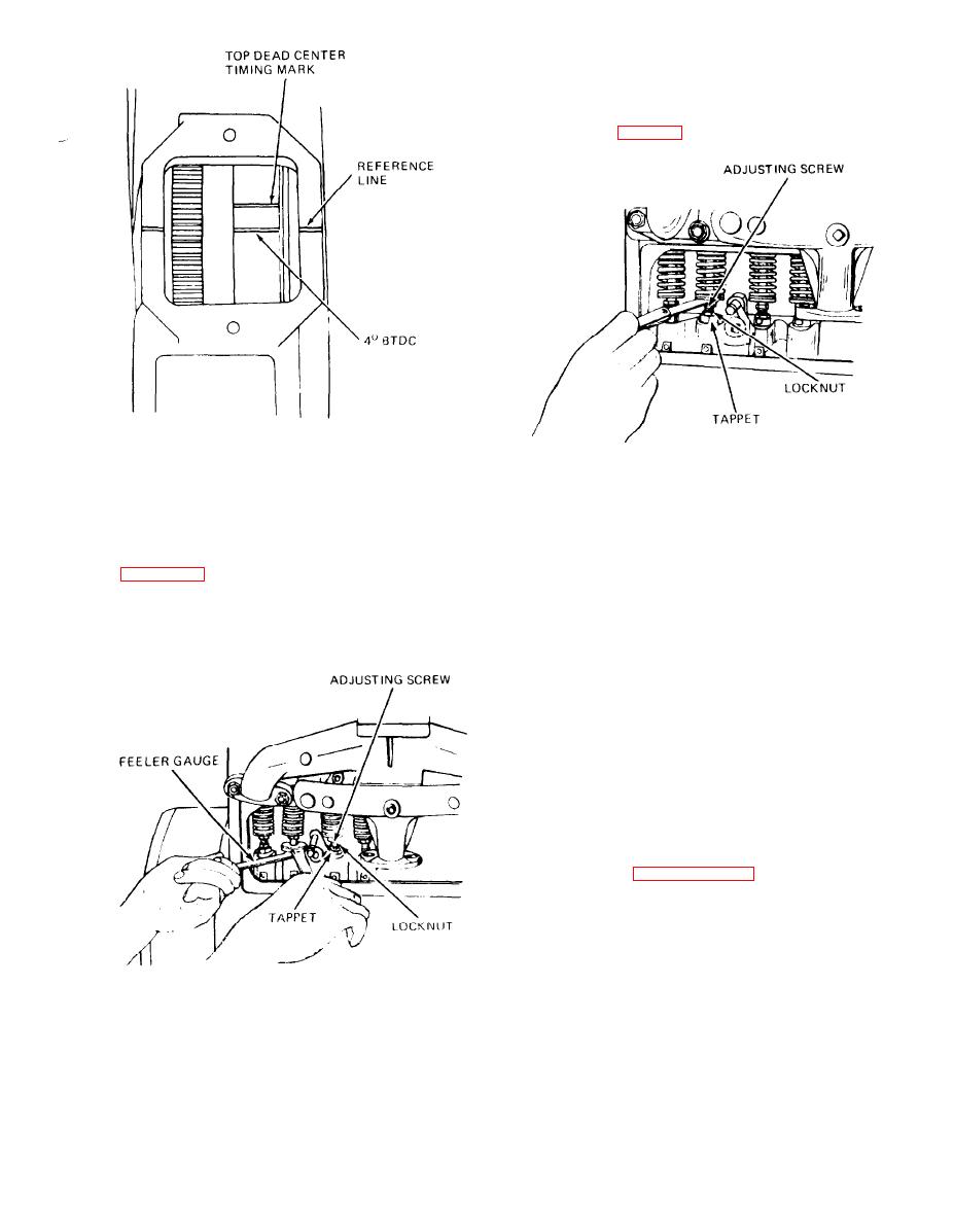
Figure 3-9. Flywheel timing marks. |
|
||
| ||||||||||
|
|
 (8) Continue adjusting the clearance until a
feeler gage of the proper thickness (0.007 to 0.009
inch for intake valves, 0.011 to 0.013 inch for exhaust
valves) will pass between the valve stem and tappet
adjusting screw (fig. 3-11) with a slight drag.
Figure 3-9. Flywheel timing marks.
(5) Use two thin open end wrenches as shown
in figure 3-10 and make the adjustment as follows:
Figure 3-11. Checking valve clearance
(6) Loosen the locknut.
(7) Hold the tappet with the lower wrench and
(9) Tighten the locknut when the correct clear-
raise or lower the tappet adjusting screw.
ance is obtained. Check clearance after tightening.
(10) Crank the engine one-half revolutions at a
time and check the clearance on each remaining set
of valves in succession according to the firing order
(1-3-4-2). Adjust valves to proper clearance if neces-
sary.
d. Install Valve Chamber Covers.
(1) Install new gaskets and valve chamber covers
over holddown studs. Secure covers with nuts and
lock washers.
(2) Covers must make oil tight seal with crank-
case. Check for leaks after starting engine.
(3) Refer to paragraph 3-31 and connect fuel
lines to fuel pump.
(4) Install timing mark cover and clamp on fly-
wheel housing.
3-26. Manifolds and Breather
the engine are a one piece casting. The carburetor is
attached to the intake manifold and the exhaust
elbow carries exhaust gases out the top of the mani-
fold. A crankcase vent valve, connected by a hose to
the engine block, carries unburned gases from the
block to the intake manifold.
Figure 3-10. Loosening valve tappet locknut.
3-15
|
|
Privacy Statement - Press Release - Copyright Information. - Contact Us |