 |
|||
|
|
|||
|
Page Title:
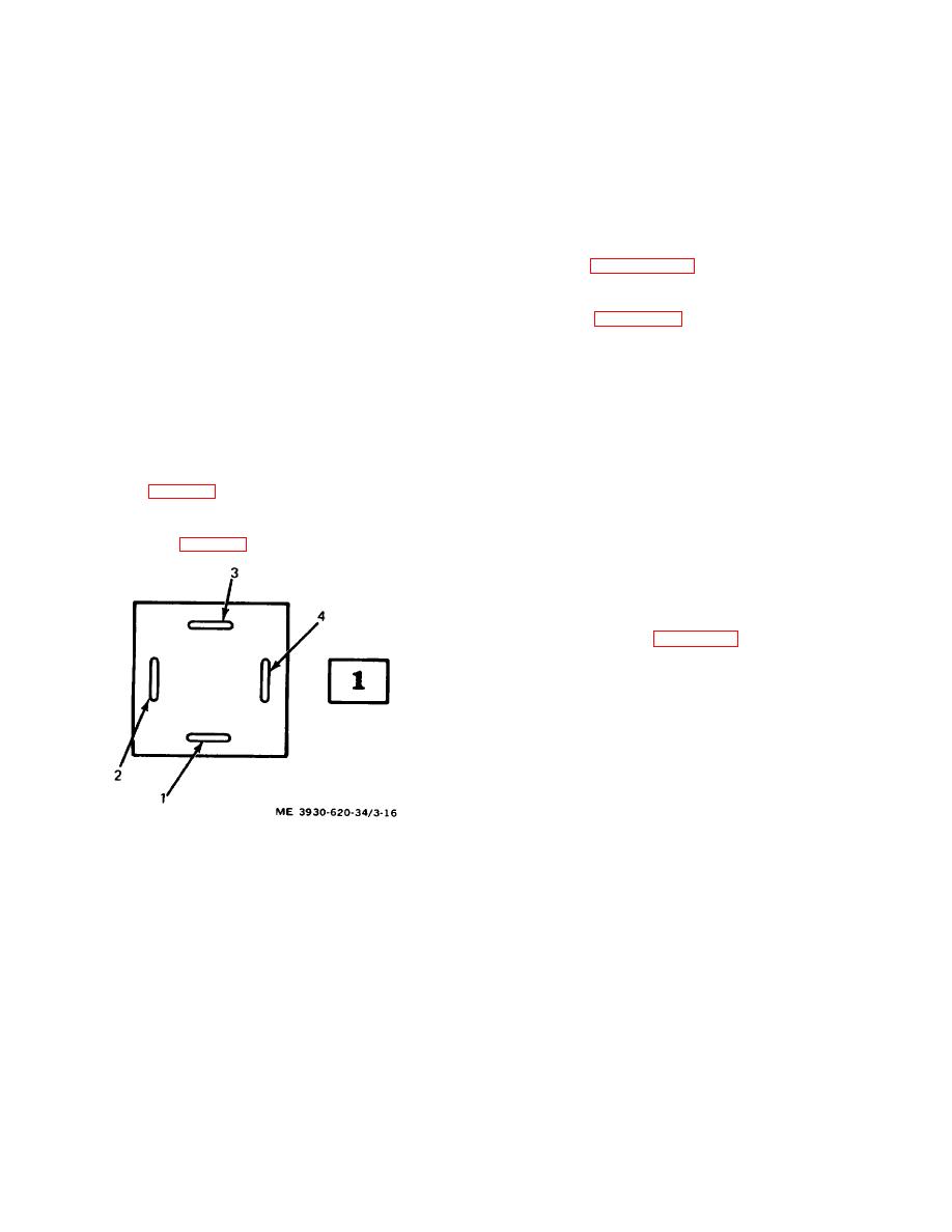
Figure 3-16. Diode bias block terminal identification |
|
||
| ||||||||||
|
|
 (4) Disconnect the lead to the A1 bus bar (27)
(4) If the voltage is incorrect, verify that the
by removing the nut, lock washer, flat washer, and
control unit is functioning by disconnecting the lead to the
screw. Connect the positive ohmmeter lead to the A1
bias block terminal 4 and measuring at the lead. It
bus bar and the negative lead to the B2+ bus bar (28).
should measure about 15 volts.
The ohmmeter should read about 70 ohms. Zero ohms
(5) Reconnect the lead. Measure for 1.5 volts
indicates a short circuit within the switch assembly. (one
10% at bias block terminal 2.
or more shorted transistors.)
(6) Measure for 3 volts 10% at bias block
To locate a shorted transistor:
(a) Remove the screw (30), lock washer
terminal 3.
(31), and flat washer (32) attaching the encapsulated
e. Removal. Remove the power switch assembly
resistor to the heat sink of the module (34). Do this for
according to paragraph 2-7.
each module, one on each side, one at a time, until the
f. Disassembly.
reading on the ohmmeter is normal. The last module
(1) Disassemble the power switch assembly
disconnected is shorted.
according to figure 3-15. A single or all power switch
(b) To check for additional shorted
modules can be removed as follows.
transistors, momentarily touch each disconnected
(a) Disconnect push-on leads (11, 12, and
resistor lead to the heat sink, one at a time. A zero ohm
13) from top and bottom of module.
reading indicates a shorted transistor in that module
(b) Remove screw (14), lock washer (15),
also.
and flat washer (16) connecting emitter lead of module to
d. Voltage Test. This test verifies that the diode bias
emitter bus bar (28).
block is functional.
(c) Remove screw (17), lock washer (18),
(1) Connect battery and turn the key switch on.
and flat washer (191 connecting each encapsulated
(2) Connect voltmeter negative lead to the B2+
resistor to collector bus bar (27).
bus bar (28, (fig. 3-15) for this test. Measure voltage by
(d) Remove nylon screw (26) and
touching the positive lead to the point indicated.
associated parts connecting each end of collector bus
(3) Measure for 4.5 to 5.5 volts at diode bias
bar (27) to end plates (51).
block terminal 4. (fig. 3-16.)
(e) Slide collector bus bar out of assembly.
(f) Loosen nuts (421 at both ends of
insulated mounting rods sufficiently to allow removal of
desired module (34).
(2) Disassemble the individual power switch
modules according to figure 3-17.
.
Figure 3-16. Diode bias block terminal identification
3-27
|
|
Privacy Statement - Press Release - Copyright Information. - Contact Us |