 |
|||
|
|
|||
|
Page Title:
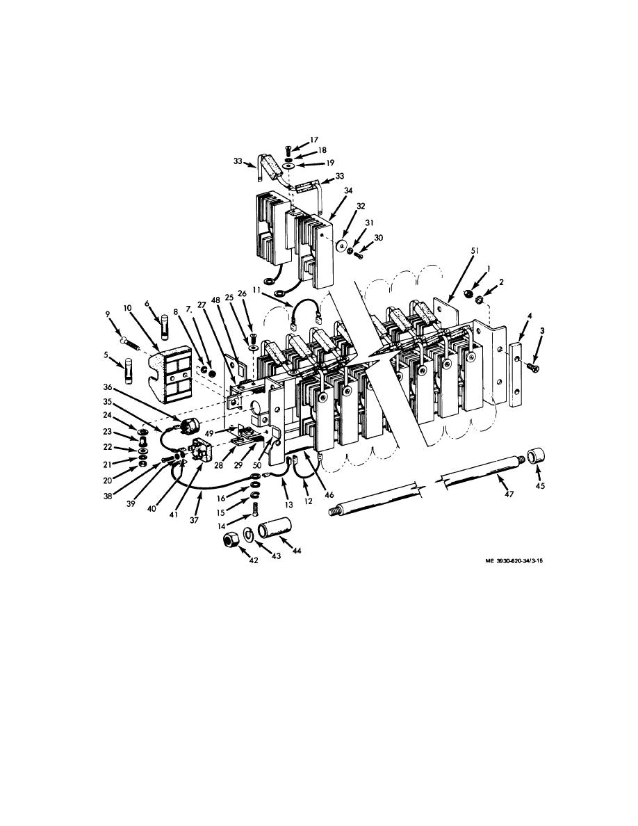
Figure 3-15. Power :switch assembly. exploded view. |
|
||
| ||||||||||
|
|
 Note. For the wire leads that are not
encapsulated resistor 33 by removing the screw (17) lock
washer (18) and flat washer (19). Check for continuity of
accessible. Check their continuity after
each resistor.
removal of the switch assembly. Unless
Note. The encapsulated resistor has a
the trouble is found in the following tests.
resistance of 0.036 ohms. Without the
(2) Remove each fuse (5 and 6) and check for
use of a milliohmmeter, however, this
continuity.
should appear as zero ohms
(3) Disconnect the center lead of each
1.
Nut
14.
Screw (12)
27,
Bus bar
40.
Flat washer
2.
Lock washer
15.
Lock washer (12)
28.
Bus bar
41.
Diode bias block
3.
Screw
16.
Flat washer (2)
29.
Bus bar insulator (4)
42.
Nut (4)
4.
Insulator (2)
17.
Screw (2)
30.
Screw (24)
43.
Lock washer (4)
5.
Fuse, 10A
18.
Lock washer (12)
31.
Lock washer (24)
44.
Spacer (24)
6.
Fuse, 5A
19.
Flat washer (12)
32.
Flat washer (24)
45.
Spacer (2)
7.
Nut
20.
Nut (4)
33.
Encapsulated resistor (24)
46.
Spacer (2)
8.
Lock washer
21.
Lock washer (4)
34.
Power switch module (12)
45.
Mounting rod (2)
9.
Screw
22.
Flat washer *4)
35.
Flexible lead (2)
48.
Marker, A1
10.
Fuse block
23.
Insulating bushing (4)
36.
Terminal bushing
49.
Marker, B2+
11.
Flexible lead (11)
24.
Nylon washer (4)
37.
Flexible lead
50.
Marker, 1
12.
Flexible lead (22)
25.
Flat washer (4)
38.
Screw
51.
End plate (2)
13.
Flexible lead (3)
26.
Screw (4)
39.
Lock washer
Figure 3-15. Power :switch assembly. exploded view.
3-26
|
|
Privacy Statement - Press Release - Copyright Information. - Contact Us |