 |
|||
|
|
|||
|
Page Title:
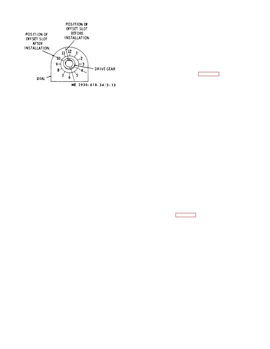
Figure 3-13. Positioning drive gear offset slot. |
|
||
| ||||||||||
|
|
 flange and screw nut into flange to a point where tube
can still be turned.
(c) Cement a new gasket on flange.
(9) Position assembled flange, relief valve,
and tube b, inserting rear end of tube in cylinder block at
No. 6 main bearing cap and placing flange against oil
pump with relief valve down.
(10)
Start rear tube nut and tighten
securely. Install and tighten the two flanges to oil pump
retaining capscrews and lockwashers. Torque to 11-13
ft.-lbs. Securely tighten front tube nut.
(11) Install oil pan (para 3-12).
g. Installation After Engine Overhaul.
During
engine overhaul, distributor and oil pump are removed
from cylinder block. In order to mesh oil pump drive gear
with gear on camshaft in original factory location, so rotor
Figure 3-13. Positioning drive gear offset slot.
in distributor will point to No. 1 cylinder spark plug wire,
proceed as follows:
(3) Insert oil pump in cylinder block with drive
(1) Rotate crankshaft in direction of engine
gear positioned as indicated in (2) above and mesh it
rotation until No. 1 cylinder exhaust valve lobe on
with gear on camshaft. Install one oil pump retaining
camshaft points horizontally to side of cylinder block.
capscrew and lockwasher and tighten only enough to
Whenever No. 1 cylinder exhaust valve camshaft lobe is
hold pump in place.
in this position, piston is on compression stroke near or
CAUTION
at top dead center and timing mark stamped on flywheel
It is possible oil pump drive gear
should be in timing hole in flywheel housing.
engaged gear on camshaft one tooth
one way or the other from correct
NOTE
position and tang on distributor drive
Number 1 cylinder exhaust valve
did not engage drive slot in pump
camshaft lobe is first lobe from front of
gear; therefore, if pump retaining
engine.
capscrews are tightened securely at
this time, undue strain will be placed
(2) Position offset slot of oil pump drive gear.
on distributor and advance arm
Refer to f (2) above.
assembly.
(3) Insert oil pump in cylinder block with drive
(4) After oil pump is in mesh with gear on
gear position as indicated in f (2) above and mesh it with
camshaft, check to make certain distributor drive has
gear on camshaft. Note that as pump drive gear meshes
engaged slot in pump drive gear and rotor is pointing to
with camshaft gear, it will rotate slightly because gears
reference mark made on side of distributor housing.
are helical type. When pump gear is fully engaged with
(5) Install cap on distributor.
cam gear, slot will be positioned at an angle of 4: 00 -
CAUTION
10: 00-o'clock (fig. 3-13). This is correct position for
Overtightening may break mounting
slot in pump drive gear to drive distributor. Install
flange. Note that flange is not flush
capscrew finger tight to hold pump in position.
(4) Insert distributor into cylinder block and
with cylinder block.
rotate until offset tang on distributor drive engages slot in
(6) Install second pump retaining capscrew
pump drive gear. In this position rotor will be pointing to
and lockwasher and tighten both capscrews to 1821 ft.-
No. 1 cylinder spark plug wire in distributor cap.
lbs. torque.
(5) Complete installation of oil pump as
(7) After pump is secured in position, check
outlined in f above.
gear backlash between pump drive gear and gear on
camshaft. Gear backlash is 0.004-inch -0.010inch, and
3-14. Oil Pressure Relief Valve
can be checked through opening at fuel pump mounting
a. Description.
Stabilized oil pressure is
pad.
maintained in engine lubrication system by an adjustable
(8) Assemble oil relief valve mounting flange,
oil pressure regulating valve located in main oil gallery at
relief valve, and oil tube assembly as follows:
front left corner of cylinder block. This valve is factory
(a) Place lockwasher on relief valve and
set to open at 35 to 40 psi. When oil pressure at relief
screw it into flange. Torque valve to 40-50 ft.-lbs. and
valve exceeds its regulated pressure setting, plunger
lock in position by bending one tab against relief valve
opens and excess oil bypasses through lower drilled
and a second tab against flange.
capscrew.
(b) Position oil tube assembly (straight section) in
3-19
|
|
Privacy Statement - Press Release - Copyright Information. - Contact Us |